
(Louis Meulstee’s web site)


Fullerphone Superposing Unit
The Fullerphone could be used over a single line and earth return or a double wire (diagram 1). Since a Fullerphone operated on DC, it was possible to work with a telephone or switchboard on the same line, a method known as superposing (diagram 2). This feature provided speech communication between the two telephones, and Morse communication between the two Fullerphones. The speech was not heard in the Fullerphones, since speech currents could pass through a Fullerphone, but were kept out of the chopper by the Fullerphone filter. The Fullerphone signals, being DC, were not heard in the telephones, blocked by the capacitors in the telephone circuit and bypassed through the magneto bell. There was, therefore, no mutual interference. The extra insertion loss was neglectable.
Apart from the simple series superposed method, there were also circuits known as superposed series and superposed phantom. These circuits were normally used on lines connecting two exchanges, requiring a Superposing Unit (One Transformer) on each side.
Superposed phantom circuit using a double wire and a Superposing Unit on each side (right). This method was the most suitable to use when a double wire was available. The Fullerphone current splitted in the winding, half flowing through each line. At the distant station the currents re-combine and return through earth.

Fullerphones connected via single line and earth return or double wire (diagram 1 above).
Superposing telephones and Fullerphones via single line and earth return or double wire (diagram 2 above)
Fullerphone Mk.IV (left) and Telephone Set D Mk.V phantom superposed using a Superposing Unit (One Transformer), as seen in the centre of the picture.


Superposed phantom circuit. Superposed series circuit.


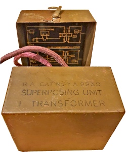
Superposing Unit side view position (above). On the lid was a tongue for clipping the unit to Switchboards UC 6-line or Frames D and P (Distribution and Protection) 10-wires.
The ‘Superposing Unit (One Transformer)’, previously known as ‘Experimental Transformer, Composition’, was a 1:1 ratio transformer having the primary and secondary windings split at a central point. (right) The transformer was toroidal wound on a special dust ring core. The inductance of each winding was 7H at 300Hz, insertion loss about 1dB.

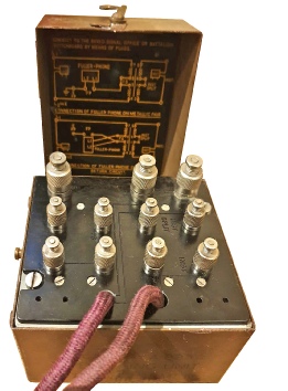
Superposing Unit (Three Transformer) No. 1A Y1/YA 4652.
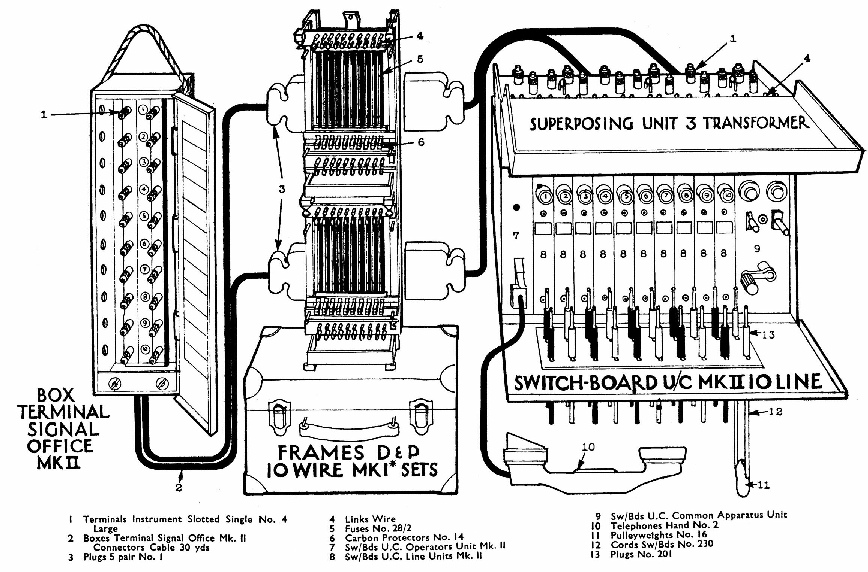
Switchboard U/C (Universal Call) 10 line, having a Superposing Unit 3 transformer mounted on top, with Frames Distribution & Protection 10 Wire and incoming lines Box Terminal Signal Office Mk.II, used in a Divisional Signals H.Q.
Superposing Unit 3 Transformer comprised basically three superposing transformers in a single metal box. It was designed to be mounted on top of Switchboard U.C. (Universal Calling) 10-line for use in Divisional Signals. The first three lines of the 10-line switchboard were normally used for superposing, providing series and phantom superposing. The ten incoming lines on Box Terminal Signal Office Mk.II were routed to Frames Distribution and Protection 10 wire to the Superposing Unit 3 Transformer
via two five-pair plugs into sockets at the rear of the superposing unit. Colour coded wires from the superposing unit connected to the line terminals of the Switchboard U.C. 10-line.
A Fullerphone, or other instrument suitable for superposing operation, was connected to slotted terminals on top of the superposing unit.
In certain cases the Frames D&P 10-wire was omitted e.g. in a Brigade Signal Office.
References:
- Signal Training, Vol. III, Pamphlet No. 20, ‘Superposing Units (One Transformer)’, 1939.
- Signal Training, Vol. III, Pamphlet No. 26, ‘Switchboards U.C. 10-line and 6-line’, 1940.
- Signal Training, Vol. III, Pamphlet No. 31, Part I ‘Boxes, Terminal, Signal Office’, Part II ‘Frames, D. and P.,
10-wire, sets’, 1940. (Reprinted with Amendments
(No. 1), 1943).
- Notes on Equipment, Volume IV, Signal and Wireless
Stores, ROAC, Donnington.
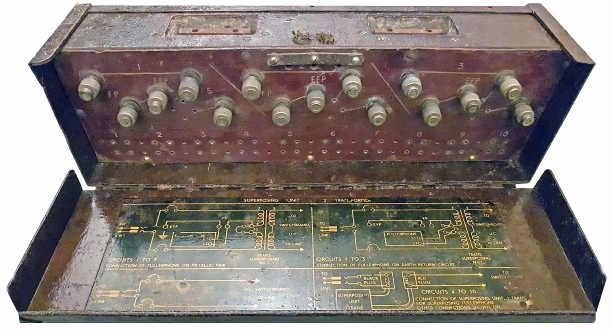
Superposing Unit (One Transformer) in opened position (Right).
The two instrument and line plug connectors were provided for connecting to Switchboard UC and Frames D and P.
‘Superposing Unit (One Transformer)’

