
(Louis Meulstee’s web site)
 Return
Electronic Fullerphone


Other electronic Fullerphones
Apart from the Tingeyphone, the German Sutel (both used operationally in World War 2) and the Canadian ‘Buzzer, Electronic’, other electronic Fullerphones were constructed in World War 2. It is unlikely whether these ever came into production, but their development is certainly of historical interest. Three ‘other electronic Fullerphones’ are described this section.
Report T63
Functional tests on four different advanced models of Canadian Tropicalised Fullerphones at S.R.D.E. and field trials at Catterick were carried out in mid 1945. The four models, incorporating a neon oscillator and a calling signal, had the same electrical circuit but differed in the layout of components, the type of case and method of carrying. The results of the trials were described in S.R.D.E. test report No. T63 (July 1945). The tests indicated that the Canadian Tropicalised Fullerphone compared very favourably in functional performance with the Fullerphone Mk.V, while being lighter and incorporating a calling device. The battery consumption was low. The sensitivity was comparable with that of the normal Fullerphone.
Trials at S.R.D.E.
Two Long Range Telegraph sets were tested at the S.R.D.E. in 1944. In the final conclusions it was stated that the sets operated satisfactory with received line currents of 200-300uA and upwards. The sensitivity of the receiver was somewhat better than that of a standard Fullerphone. Long range was achieved only by increasing the voltage of the sending battery.
The audio output of the instrument in the headphones was considered too high and its use over long periods would be tiring to operators as no means of reducing the output was provided. The instrument compared favourably with the Fullerphone as regards security and freedom of interference.
The set did not appear to have been designed to meet tropical requirement, and was found not suitable for use under tropical conditions. The weight and size of the instrument were considered as excessive. The working life of the LT battery was estimated as 150 hours. The lives of the HT and GB cells would be a little less than their shelf lives.
The Long Range Telegraph Set (N.Z.) was developed in New Zealand probably in late 1943 or early 1944. It fulfilled the functions of the Fullerphone, operated on the same principle and was suitable for working over the same types of circuits. Considering its name, it is believed that the instrument was primary intended for communication at a telegraph office over very long static lines.
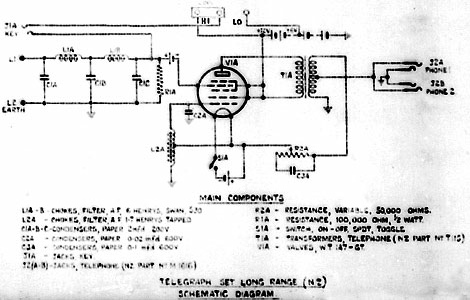
Circuit diagram of Long Range Telegraph Set (N.Z.). This diagram was taken from a microfilm and the represented the best which could be achieved. It should be noted that the general principle resemble that of the Tingeyphone.
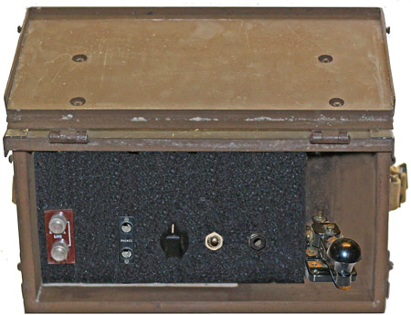
Mock-up constructed with the aid of Adobe PhotoShop showing of how the Long Range Telegraph Set (N.Z.) might have looked. (The box used for taking this picture was a Canadian Wireless Remote Control which had approximately similar dimensions).
The chassis was housed in a steel case in which the Morse key was mounted in the operating position. The case had two internal compartments, a small one on the right hand size to hold the signalling key and headphones, and a larger one into which the chassis slide. One heptode valve type 1A7GT was used as oscillator and modulator, a spare valve was carried internally. Access to the inside of the chassis was obtained by unscrewing a single captive screw on the front of the main panel.
The ‘Australian Telecommunications Summary’, a publication reviewing the developments of Australian signals during World War 2, wrote in 1946: ‘..late during the war years and in line with developments overseas, experimental work was carried out by the Australian Military Forces to produce a design in which the mechanical chopper of the Fullerphone was replaced by an audio frequency oscillator. As in the Canadian design (on which the work was based) one miniature valve was employed, together with a 12 volt ‘mini-max’ HT battery. The complete unit plugged-in to replace the standard buzzer. Final operational field tests of the rather protracted project were still in progress as at August 1945, and were eventually abandoned in view of the more promising nature of reports on new overseas instruments..’
Long Range Telegraph Set (N.Z.) 1944
Canadian Tropicalised Fullerphone (1945)
Developments in Australia
During late September 1944 a design project of a tropicalised lightweight miniature Fullerphone was initiated in Canada, given a priority rating AAA.
Development proceeded concurrently by C.S.R.D.E. and the Northern Electric Co. A neon tube oscillator feeding a metal rectifier modulator bridge was used to provide a chopping action instead of the mechanical buzzer-chopper used in the Fullerphone. A calling signal was provided by application of the HT voltage (about 100V) to the line and this would light a neon tube signalling lamp at the distant end. By December 1944 two C.S.R.D.E models were completed and under test. Prototypes were ready in March 1945; these were demonstrated to General Staff on 1 May 1945.
The neon oscillator system was preferable to the thermionic valve oscillator as used in the Canadian Buzzer Electronic mainly due to the lower current consumption. The use of a neon calling lamp had the advantage that it did not produce a signal on a series telephone but it had two serious disadvantages:
- The high voltage to the line might lead to breakdown under conditions of low line insulation resistance.
- Continuous watching would be required at the Fullerphone in the standby position. Field trials with similar systems (Adapter Plug U-4/GT which incorporate a neon tube), indicated that the effort of continually watching for a signal was a great strain to the operator.
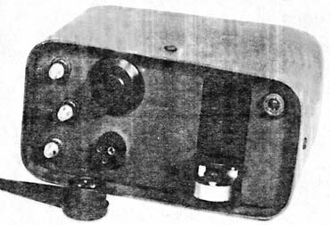
Overall view of Canadian Tropicalised Fullerphone. Of interest was the foldable Morse key. The controls included an on/off switch, Morse key, bridge balance (probably an internal control), line balance (to eliminate DC series emf in the line, similar to the potentiometer/switch in the Fullerphone. A special 110.5V battery was fitted in the back of the case.
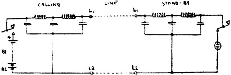
Functional diagram of calling arrangements of the tropicalised Canadian Fullerphone. A full circuit diagram of the instrument was not found.
The only criticism was the use of a 3-point plug and socket which was previously fitted in the Wireless Sets Nos. 38 Mk.III and 78 but its design was found unsuitable and replaced by a new type with two or three contacts (as used on the R209 and later WS No. 88). In spite of favourable reactions from all quarters to this development, it was pointed out that the adoption of the equipment by War Office was very problematical. There was no General Service requirement, the cessation of hostilities and economic factors did not improve the possibilities of a requirement ever materialising, except as a long-term proposition.
Circuit description.
Transmitting
When the Morse key was depressed the line battery was connected to the line through a filter network. The filter fulfilled the same function as in the Fullerphone. The operator could hear his own signals via the ‘receive’ function of the circuit.
The operating range could be varied by a link. For SHORT range the link (LO) connected the battery to provide 6V. For MEDIUM range the HI link was provided to give 12V. For long range an external battery could be connected in series with the internal 12V battery.
Receiving
A type 1A7GT heptode valve was connected to form an audio oscillator with a frequency of approximately 1000Hz. The grid battery voltage of 1.5V applied to the fourth grid reduced the anode current to almost zero, and normally suppressed oscillation. A DC signal of correct polarity, applied to the control grid would, if of sufficient voltage, cancel the bias and allowed the valve to oscillate. The oscillation was partly controlled by a variable network in the load circuit.
It was found that earth currents would cause interference, but not to the same degree as in the Fullerphone.

