(Louis Meulstee’s web site)


Fullerphone principle of operation
armature, and hence, the operating speed was higher than the Buzzer telegraph. The Fullerphone should not be compared with other DC telegraph systems and Buzzer telegraphs, since its operation principle differed considerably. The Fullerphone employed direct current in the line. By means of a chopping device and a filter circuit the current which flows in the headphones of both transmitting and receiving Fullerphones was interrupted at an audible frequency (about 400 to 550 Hz). That means that no call could be received (or side tone be heard) unless the chopping device (also known as Buzzer-Chopper) was working and properly adjusted. Therefore it was essential that the Buzzer-Chopper was always running whether transmitting or receiving. Adjustment of the Buzzer-Chopper was not a difficult job, but required some proficiency from the operator. (See ‘Using the Fullerphone’)

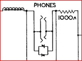
Simplified circuit diagram of the Fullerphone. When in operational use, the polarised Buzzer-Chopper was always running comprising a driving contact 'B' and a chopping or interrupting contact 'K'.

Transmitting.
When transmitting, the Buzzer-Chopper was kept working as on reception. If the circuit was closed at contact K and the Morse key was pressed, a current from the battery flowed through contact K, the headphones, the chokes CH1 and CH2, and the line to the distant Fullerphone. At the same time, the condensers C1, C2 and C3 were charged to the voltage of the battery. When the circuit was broken at contact K, no current could flow from the battery or through the headphones. But the condensers were now able to discharge and send a current to the line in the same direction as the battery current. The combined action of the chokes and condensers thus maintained a steady flow of current to the line as long as the key is pressed in spite of the fact that the battery current is being continually interrupted at contact K. This arrangement enabled the sending operator to hear his own signals in his headphones.
Potentiometer.
A potentiometer was used for balancing out certain forms of DC earth potentials which might be picked up by the Fullerphone line circuit, notably on those where the earth was used as return line. Such a DC potential resulted in a current flow which was heard at the same frequency as the signals, thereby disturbing them. The potentiometer was energised by an independent 1.5 volt dry battery and connected through a reversing switch (see the circuit diagram) so that a voltage could be impressed in the line equal and opposite to the voltage which was causing the interference. As the currents picked up would not necessary be the same at each end of the line, each Fullerphone station had to adjust its own potentiometer to suit the earth current received. In normal operation, the potentiometer was not required and the reversing switch left in the centre position.
Overhearing
A filter combination of chokes and condensers prevented any variation in the line current during a signal, and prevented any audible frequency currents produced either by induction from other lines or by a buzzer or telephone speech on the line from passing through the headphones. It also ensured that the rise and fall of line current was comparatively slow and thus prevented clicks being heard in the receiver of a telephone set superposed on the same line. Therefore, the Fullerphone could not be overheard either by induction or earth leakage, and was only be tapped by a similar instrument directly connected to the line. It was found that with the use of very sensitive equipment (believed to be a valve amplifier) it was possible to overhear a Fullerphone when the listening earth was within 180ft of the Fullerphone earth.

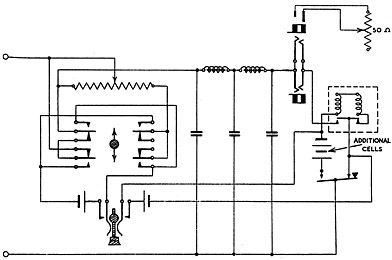
Circuit diagram of Fullerphone Mk. IV* which was identical to the pre-war Mk.IV model, but modified with interference suppression. (C4-7 and R1-2). The modified buzzer was renamed Buzzer F Mk.II*.
What is a Fullerphone and how does it work?
The Fullerphone was basically a DC line Morse telegraph. The main feature of the Fullerphone was that the transmissions were practically immune from overhearing, which made the system at the time when it was devised very suitable for use in forward areas. In addition, the Fullerphone was very sensitive and a line current of only 0.5 microampere sufficient for readable signals. In practice, however, 2 microamperes were required for comfortable readings and it could be worked over normal Army field lines 15-20 miles long. When superposed on existing telephone lines, telephone and Fullerphone signals could be sent over the line simultaneously without mutual interference
It should be noted that Fullerphone signals were much clearer than those of a 'Buzzer telegraph' as the start and end of a signal did not depend on the starting and stopping of a vibrating
Reception.
If a DC voltage was applied between the L1 and L2 terminals and the circuit was momentarily closed at contact K, a current will flow through the choke coils CH1 and CH2, the headphones, contact K and the Morse key. When the circuit was broken at K the current cannot flow through the headphones but will flow into and charge the condensers C1, C2 and C3. If the circuit was again closed at K the condensers partially discharge through the headphones. Therefore when the chopper was working, an intermittent current at audible frequency flowed through the headphones while the line current alternately flows through the headphones and into the condensers. The line current remains practically constant. Thus Morse code dots and dashes sent by the single current Morse key at the distant Fullerphone were received as short and long notes in the headphones while the current in the line was of much the same nature as that sent by a single current Morse set. The line current in this case, however, was very much smaller, and clicks were not perceptible due to the smoothing action of the filters in the Fullerphone.
Improvement of signal to noise ratio on Fullerphone Circuits.
(R.Signals Training Memorandum No. 4, February 1943)
Stray AC voltages induced into a Fullerphone circuit may cause serious interference with the reception of signals. This could be overcome by increasing the signal in the line by means of additional cells at each instrument, and to reduce the strength of the received signal to the normal value by means of a potentiometer across the telephones. The noise level was also reduced by the potentiometer to such an extent that it no longer gave rise to serious interference.
The modifications to the circuit are shown in the circuit (left).
The positive terminal of the additional cell or battery was connected to the back (make) contact of the key, and the negative terminal to the lead which was normally joined to the contact. The number of cells required was determined by experiment, a single cell being tried first. A potentiometer of 50 Ohms was connected to a pair of leads which were connected to a plug inserted in one of the telephone jacks. Since the increased line current employed renders the signals more easily intercepted, it was advised to employ this method only if there was little risk of interception being attempted.
A similar method of improving the signal to noise ratio on a Fullerphone circuit was incorporated in Fullerphone Mk.IV* Special (Aust.) with Unit Fullerphone Long Range (Aust.). See HERE for details.
Fullerphone Mk.IV, Mk.V, and Mk.6 had a crash limiter comprising two rectifiers connected back to back across the terminals of the phone's jack. It reduced acoustic shock from ringing currents when a Fullerphone worked in series with a telephone


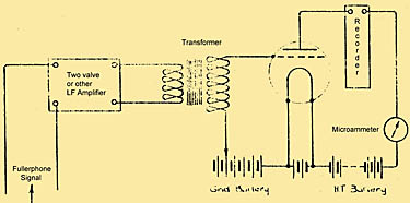
High speed Fullerphone land telegraph.
Various methods for recording at high speeds using Fullerphone signals were tried during World War 1 and later. The best results were obtained by using an amplifier followed by a rectifier valve. The recorder was operated by the anode current in this valve. This recording instrument was an undulator or a similar instrument directly recording the changes in the anode current.
(Information and circuit diagram taken from SEE Experimental No. 346 Report No. 1, 8-5-1919, Major A.C. Fuller).