(Louis Meulstee’s web site)
Previous
Return
Next
Wireless Set No. 17
Wireless Set No. 19 special
Wireless Set No. 19 Italy
Wireless Set No. 38 Mk.II
Wireless Set No. 46
Wireless Set Cdn No. 58
Wireless Set No. 62
Wireless Set No. 88
Wireless Set No. 48
Wireless Set No. 18
Amplifier RF No. 2
Wireless Set No. 38afv
Wireless Set No. 38 Mk.3
Wireless Set No. 12


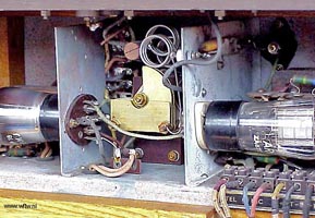
Close up view of transceiver chassis Wireless Set No. 17.
Note AF valve type ARP18 left and RF valve type AR6 fitted on the right hand side.
In the centre were the main tuning condenser and RF tuning coil. The microphone and
headphones were permanently connected to the set.
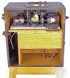
Wireless Set No. 17 rear view.
The top section of the oak wood cabinet was taken by the transceiver chassis. In
the bottom section was space for two 60V dry batteries (right hand compartment),
and a 2V 16Ah accumulator (left hand compartment). Various types of aerials could
be connected to sockets and terminals fitted on top of the set.
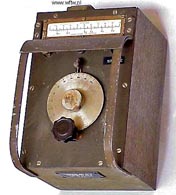
Wireless Set No. 17 Wavemeter Mk.II. ZA 171133.
Because the tuning scale of a No. 17 Set was not calibrated in frequency, an absorption
type wavemeter was supplied for use at a Control Station. The wavemeter fitted on
its side with the wooden projection facing into the back compartment of the set near
the RF coil. In the SEND position, the transceiver dial was tuned until maximum glow
was observed in the wavemeter lamp
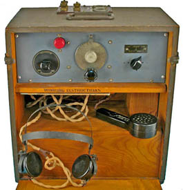
Wireless Set No. 17 was a portable transceiver used as a ground station for communication
between searchlight Section HQ and detachments, AA batteries or Royal Engineers detachments.
Frequency range 44-64MHz. MO control. RF output 0.3W. R/T only. Range up to 15 miles.
The aerial was a half-wave dipole with optional reflector.
Front panel view of Wireless Set No. 17.


 Next page


 Previous
Return
Next
Wireless Set No. 17
Wireless Set No. 19 special
Wireless Set No. 19 Italy
Wireless Set No. 38 Mk.II
Wireless Set No. 46
Wireless Set Cdn No. 58
Wireless Set No. 62
Wireless Set No. 88
Wireless Set No. 48
Wireless Set No. 18
Amplifier RF No. 2
Wireless Set No. 38afv
Wireless Set No. 38 Mk.3
Wireless Set No. 12


 Next page

