(Louis Meulstee’s web site)
 British WW2
Australia
Germany WW1
British WW1
Italy
France
Dutch
USA
Portugal
British WW2
Australia
Germany WW1
British WW1
Italy
France
Dutch
USA
Portugal
 Next page (German World War 1 Utel)


USA Buzzerphone model P-1917, EE-1 and EE1-A
From ‘Report of the Chief Signal Officer 1918’
In 1917 Capt. Paddock, Signal Corps, in charge of field equipment engineering at general headquarters, adapted the Fullerphone of the British Army for construction along lines suited for our use. In conjunction with the Western Electric Co., Capt. Paddock developed the Buzzerphone, model P-1917, which was produced in the factory of Western Electric Co. at Paris.
Samples of te Buzzerphone were furnished in the United States and development and improvements were taken up by the Western Electric Co. resulting in the production of a Buzzerphone which was an improvement over to set manufactured in France. This set (the Buzzerphone EE-1 and later EE1-A) was not ready for service at the signing of the armistice. The ‘howler’ receiving device was a distinct improvement over the buzzer/chopper device previously used by the British and American forces.
An entirely new design in the form of a potentiometer, in which no reversion key was necessary, was developed for use with the later variation of the instrument. The operation of the handle gave positive or negative currents on the line of potential as desired.
Further improvement to make the insulation of the set more satisfactory is necessary, and work on this line could be taken up to advantage.
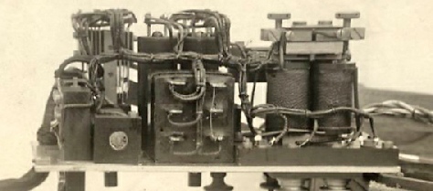
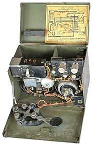
Internal view of Buzzerphone model P-1917 showing the buzzer/chopper on the right hand side.
Buzzerphone model P-1917 was produced in Paris by L.M.T., a French factory, for the Western Electric Co. The front panel was hinged to allow easy access to the buzzer/chopper.
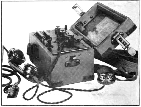
Buzzerphone model P-1917 was fitted in a strong mahogany box. The batteries were placed in clips at the bottom. The single headphone, used for Fullerphone operation, was permanently connected to the instrument. When not in use it was stored in a compartment at the right hand side.
Buzzerphone model P-1917
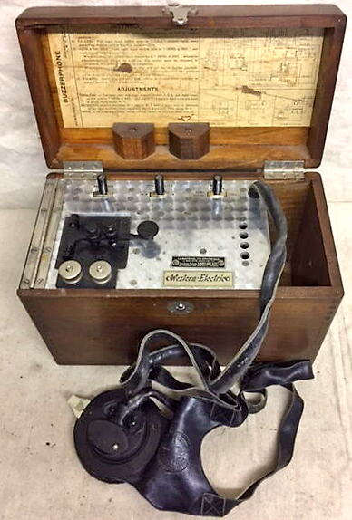
Buzzerphone EE-1
A buzzerphone model P-1917 was sent to the USA in order to put in production there. Steps were taken to redesign the instrument to overcome a few undesirable features such as the sensitive buzzer/chopper (the latter also described as Interruptor). An entirely different type of buzzer, utilising the principle of a ‘howler’, composed of the telephone receiver and microphone, was deviced. This produced a higher frequency, and in addition the circuits were modified, slightly increasing the line current. The telephone functionality was retained with a plug-in handset, calling was done by a separate buzzer. The size and weight of the instrument (built into a wooden box with reinforcements on the edges) were also reduced.
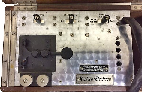
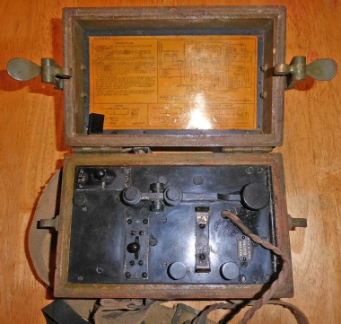
A new design in the form of the potentiometer, in which no reversing key was necessary, was developed for use with the EE1-A. The operation of the handle, to the right or the left from its neutral point gave positive or negative currents on the line of potential as required. The telephone function was omitted in this later variation. The EE1-A did not differ very much from the earlier Buzzerphone EE-1; the external visual differences were the absence of the telephone handset socket and fitting of a potentiometer key.

Buzzerphone EE1-A

Telegraph Set TG-5
The Telegraph Set TG-5, used in World War 2, was a portable DC field set for telegraph communication over short distances. It should be noted that it operated on a completely different principle to the Fullerphone and Buzzerphone.
A sensitive line relay BK-7 actuated interruptor BZ-5. The latter was based on the howler, as used in the Buzzer-phone EE-1 and EE1-A.
For reliable communication the TG-5 required at least 1mA line current whereas the Fullerphone would need much less.
4-pt socket for handset

Buzzer telegraph receiver
Howler unit
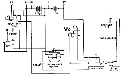
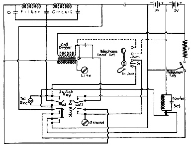
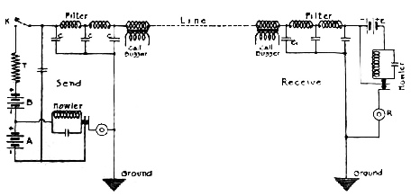
Simplified functional diagram of the Buzzerphone EE-1 and EE1-A (above), and circuit diagram of the Buzzerphone EE-1 Right)
Send-receive, normal, and call switching key
Potentiometer key
Send-receive, normal, and call switching key.
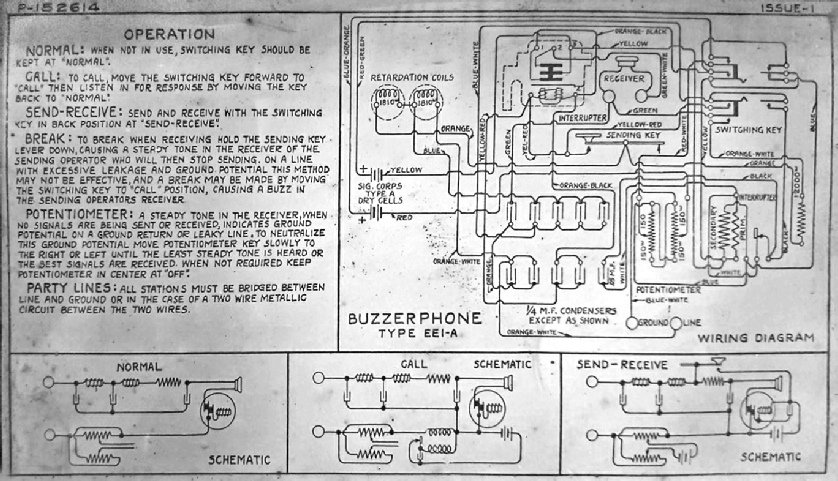
Circuit diagram and operation instructions of the Buzzerphone EE1-A (below)
Howler unit BZ-5
Relay BK-7