
(Louis Meulstee’s web site)
 British WW2
Australia
Germany WW1
British WW1
Italy
France
Dutch
USA
Portugal
British WW2
Australia
Germany WW1
British WW1
Italy
France
Dutch
USA
Portugal

Fullerphone Mk.III, No. 13039, manufactured in 1920 by W/T Factory WD, Teddington, S.W. (above)
- Fullerphone Trench ‘D’ and ‘F’. The Trench D was a converted D Mk.III telephone with an external 1,5V call and speech battery, connected by flexible leads. The Trench F was similar but fitted in a wooden case.
- Fullerphones Trench ‘S’ and ‘W’ were similar in design having just minor wiring changes. Electrically they were quite similar to the Trench D and Trench F but differ in mechanical construction.
- Fullerphones Office Mk.I and Mk.I* were fitted with a potentiometer and reverse current switch.#
- Fullerphones P.O. Types Marks 234 and 235, were produced by the Post Office. #
- Fullerphones P.O. Types Marks 237, 237a and 273b were produced by the Post Office.
- Fullerphone Mk.III was developed towards the end of World War 1. It remained in production until the late 1930s.
It should be noted that no signals were heard in the receiver (headphones) when the key was pressed in the models marked #.
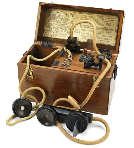
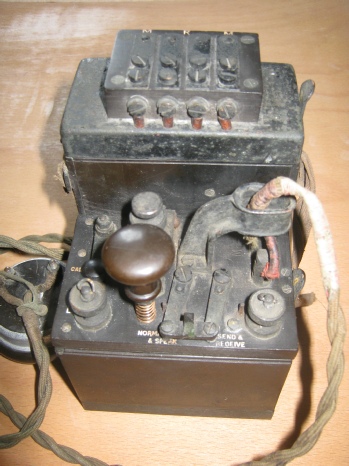
The Fullerphone Mark III (left and right) was developed in late World War 1. It was the standard model in the inter-war years, until being superseded by the Fullerphone Mk. IV which became available in about 1937. A telephone and calling buzzer facility were fitted in the Mk.III model; these were of course liable to overhearing. Note the folding type Morse key in the bottom right hand corner of the case. This model was fitted with a potentiometer and reverse current key. The main instrument was mounted in a canvas covered wooden carrying case, provided with a protective lid.
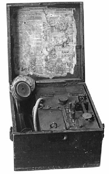
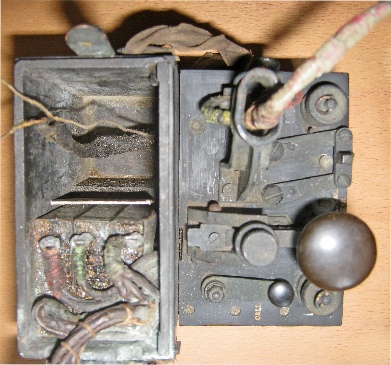
Fullerphone Office Mk.I*. (Left and below). This model was manufactured in 1916 by Siemens Bros. The Morse key was fixed-mounted on the control panel along with a reverse current switch and potentiometer.


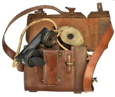
Fullerphone Trench D
Fullerphone Mk.III removed from its carrying case.


a.jpg)
British World War 1 Fullerphones
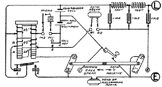
Circuit diagram of the Mk.III Fullerphone.
The known refinements such as reverse current potentiometer and hearing own send Morse were incorporated in this model. Note that the telephone handset could be removed by a 4-point plug and socket.
The Trench D is a converted Telephone Portable D Mk.III, with the call & speak cell external, connected by flexible leads, carried in its original leather case. The Trench F is in a wooden case.
Outgoing Fullerphone signals are heard in the head receiver, but not in the hand telephone. Outgoing calls are heard in both receivers.
Incoming Fullerphone signals and calls are both received in the head receiver. Speech can be received in the telephone receiver as well as in the hand telephone. The buzzer current goes through both A & B coils but the primary calling current goes through coil B only. The secondary calling current has to pass through the battery on its way out to line. While Fullerphoning the hand telephone must not be plugged in or a loud buzz is heard in both receivers while switch is at send & receive. (Original WW1 text of circuit diagram)


Fullerphone Trench S & W
General view of Fullerphone Trench D. The 4-pt contact block on top was for connecting the handset.
The Fullerphone single headset was permanently connected.
Externally the D Mark III telephone and the Fullerphone Trench D were identical.
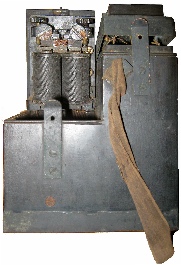
The buzzer/interruptor was fitter under the control panel which could be lifted for adjustment of the contacts.

Top view of Fullerphone Trench D with battery compartment opened showing that the space for the call and speak battery is taken by the filter circuit.
Fullerphone Post Office 234, 235, 237
Leather case for the Fullerphone Trench D and Telephone D Mk.III.
Circuit diagram of the the Fullerphone Trench D.
The Fullerphones Trench S (Siemens Bros) and W had the same wiring diagram except that in W the connections 4 and 5 are reversed.
Outgoing Fullerphone signals are heard in head receiver but not in the hand telephone. Outgoing calls are heard in both receivers. Incoming Fullerphone signals and calls are both received in head receiver. The calls having to go through coils B & A on the way.
Incoming calls are also received in hand telephone, when plugged in, but not Fullerphone signals. Speech can be received in the Fullerphone receiver as well as in hand telephone. The buzzer current goes through both A & B coils, but the primary calling current goes through coil B only. The secondary calling current has to pass through the battery on its way out to line. While Fullerphoning the hand telephone must not be plugged or a loud continuous buzz is heard in both receivers while switch is at send & receive. (Original WW1 text of circuit diagram)


Post Office types Fullerphones Marks 234, 235 and 237 were specifically built as a Fullerphone, with speech facility. In the 234 and 235 the induction coil was used for calling as well as speaking.
In the Post Office types Marks 237, 237a and 237b the induction coil was used for speaking only. For calling the buzzer was used alone on the same principle as in a vibrator telegraph.
Fullerphones Office Mk.I and Mk.I*
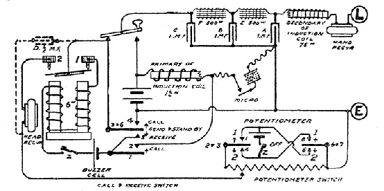
Fullerphone Mark III
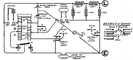
The circuit diagram is for the Mk.I*. In the Office Fullerphone Mk.I capacitor A is 2 uF, capacitors B and C are omitted and D added. Also choke coil E is 200w and choke coil F is omitted. Later issues of both Marks have no potentiometer.
The call is received in hand receiver, Fullerphone signals in head receiver. Outgoing Fullerphone signals are inaudible in either receiver. You can speak and Fullerphone at the same time but the speech can be overheard. On closing the box, the lid opens switches Z and Z. (Original WW1 text of circuit diagram)

Fullerphone Trench W.
Fullerphone Trench S.
Fullerphone Post Office Mark 235

