
(Louis Meulstee’s web site)


.")
.")


Larkspur era Control Harness image directory.
Junction Box One Set J1
Control unit C Ops box
Control unit D Drv box
Junction Box Two Set J2
R Control unit R box
Rebroadcast unit B box
Junct Box Three Set J3
Adapter unit E box
Adapter unit A box
Adapter unit T box (6)
Adapter unit O box
M Rebroadcast MRRB
IC Amplifier I box
R C Unit K box
R C Unit K Mk.2 box
R C Unit K Mk.3 box
Remote handset
ALS 19

The ‘Larkspur’ era range of equipment was usually controlled through a system of control boxes known as Wireless Control Harness type ‘A’ or type ’B’. On this page is an overview of the commonly used types of control boxes and junction boxes.
Wireless Control Harness.
An AFV carrying Larkspur era equipment had usually up to three radio sets, and an intercom (IC) system. The crew, depending on the model of vehicle, could be anything from two to six men. Any member of the crew would need to use any of the communications systems at any time. The system of control boxes, distribution boxes and interconnection cables which enabled this to be done was called the Wireless Control Harness (later known as Control Harness. Although principally intended for use in a vehicle, it was used in installations which had been dismounted and set up as a ground station. The Wireless Control Harness concept was not new as with the entrance of the Wireless Set No. 19 in 1941, a similar harness was introduced controlling two radio sets and providing intercommunication in an AFV.
Two types of harness were in service for the Larkspur era range of equipment.
Wireless Control Harness type 'A'
was of a rigid design which allowed strict use of all control units concerned. It was principally used in all tanks and Saracen ACV's with two or three-set installations. This harness was very expensive and not very flexible for use in other applications. The 'A' harness was essentially a small automatic switchboard fitted in the main
Junction Distribution JD9 box. To this box were connected up to three radio sets andall the control units, (No. 30, 31, 34 and JD 8) each of which allotted to a crew member.
Various other boxes were added later e.g. to provide Clansman equipment to be connected to the existing Larkspur 'A' harness and visa versa. The advantage of this system was that, in an emergency, the commander could push a button which would send an over-riding signal to the JD9 box, and all selected circuits automatically switched their crew members to intercom, irrespective of the setting of the crew member's control units.
This system was necessary for tanks, but not for use in other vehicles. It was for this reason that the much cheaper and flexible 'B' harness was used elsewhere.
Wireless Control Harness type 'B'
was designed for use in Fitted For Radio (FFR) 'B' type vehicles, ground stations, FV 432 vehicle series and in armoured cars. This harness was principally for the control of one or two sets, very flexible, variable in content and layout, and at the time the most common harness in use.
The 'B' harness was made up of a series of junction boxes, additional control units and connector leads.
A Commander's Headgear Assembly counted as a control box as it was virtually a Crew Member's Headgear Assembly and a Control Unit 'C' combined. Leads connecting headgear assemblies to boxes were 6-point. All controls were designed to enable switches and controls to be manipulated by operators even when wearing heavy arctic protective gloves.
The units of the Wireless Control Harness type 'A' and 'B' were contained in fully sealed cast aluminium boxes and capable of withstanding the severe conditions in the field. All leads interconnecting the boxes were Plessey type Mk. 4 multi-point plugs and sockets.
Radio sets which were designed to be controlled by the Wireless Control Harness type 'A' or type 'B' included the Station Radio B47, B48, C42, C45, C11/R210, C12, C13 and by means of a special adapter connector other (older) sets such as Wireless Set No. 19 and Station Radio BE201.
It should be noted that within the Royal Armoured Corps the use of sets (as indicated on the control panels of the harness boxes) controlled by a three set harness was standardized: the 'A' set for the forward net, the 'B' set for rearward net and the 'C' set for communication to supporting forces.
Junct Distribution No. 9
Control Unit No. 34
Control Unit No. 30
Control Unit No. 31
Junct Distribution No. 8
Wireless Control Harness type ‘A’ boxes.
Wireless Control Harness type ‘B’ boxes.
LT Distribution boxes
LT Distribution boxes
Test Unit M box
Radio Set DM box
RC DM box RCDM
Goodman box
R T Adapter
Applique Unit B
Applique Unit D
Adapter unit T box (12)
Operator’s micr assy
Headset
Larkspur era ancillaries and test equipment.
Functional Tester FT-1
Functional Tester Ft-2
Simulator
IBGC box
RSB2 box
IBRA test box
IBRA box
Test set radio
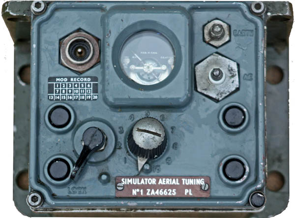
Simulator Aerial Tuning
Colour photographs courtesy Chris Jones, G8GFB, and Andy Osborne, G8JAC (or otherwise stated).
Simulator Aerial Tuning
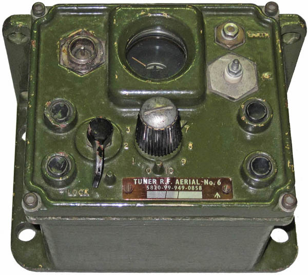
Tuner RF Aerial No. 6
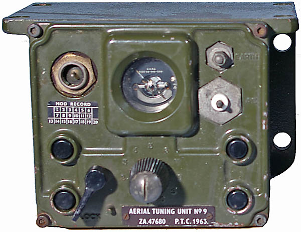
Tuner RF Aerial No. 9
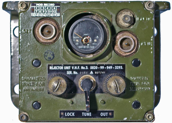
Rejector Unit VHF No. 3
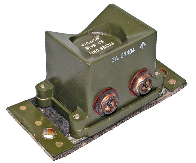
Filter Unit RF No. 15

