(Louis Meulstee’s web site)
 Home
Return
ASR 1
ASR 2
ASR 3
ASR 4
Home
Return
ASR 1
ASR 2
ASR 3
ASR 4


Gibson Girl part 2. Air-Sea Rescue: Moving to VHF

Airborne lifeboats
From 1943 onwards, rescue operations were also carried out by Hudson, Barracuda and Warwick aircraft carrying airborne lifeboats. The 27ft long airborne lifeboat was dropped by parachute, basically to ditched crews which were out of reach of rescue launches. The boat was mainly made of plywood and had (beside the sail) two engines, navigation equipment, supplies of food and water, and a radio transmitter and receiver, both operating on 500 kHz. Its weight fully loaded was 1200 lb. In order to keep the boats head in the wind, a sea anchor was fired during the descent. Two buoyancy chambers were automatically inflated as the boat left the aircraft.
The emergency transmitter was a BC-778-A Gibson Girl (fixed mounted on a special mounting plate), and a receiver (R-1545) providing two way telegraphy communication. Normally the kite aerial was employed but alternatively a fixed emergency aerial running through the mast could be used. No balloon aerial was used with this type lifeboat radio station. A separate aerial winch type 10 (thus not the one fitted on the Gibson Girl) was used for paying out the aerial wire attached to the kite. It was normally placed in position into a forward rimlock socket on either side of the boat, the choice depending on the direction of the wind .
Receiver R-1545
The R-1545 was a self contained conventional TRF receiver with one RF stage principally for 500kHz operation, but tunable from 470 to 530 kHz. The receiver was mounted in a resin-bounded plywood case and a detachable lid. It used type ARP12 or VP23 valves throughout, and operated on an internal dry 45 V HT battery and 2V LT accumulator. An interesting feature was the provision of a socket type 359 (‘8’ in the picture left) for connection of the operator's own flying helmets phones should the provided headphones fail.
‘WALTER’
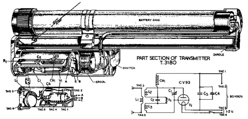
Transmitter Type T-3180 or 'Walter' was a British Air-Sea Rescue homing beacon. Owing to its compactness and very light weight it was used in virtually any type of life-saving craft including single-seater dinghies type K, Q and S. It operated on the Air to Surface Vessels (ASV) radar frequency of 177 MHz. Its signals could be received by airborne ASV Mk. II radar sets or Rebecca Mk. IIb equipment in Coastal Command and Fleet Air Arm aircraft.
The T-3180 ‘Walter’ was a self-contained unit comprising a battery in waterproof case, aerial mast and a small oscillator/aerial unit. The power supply was fed from the battery case on the bottom to the oscillator unit by a length of cable running alongside the mast. An on-off switch was located on the battery case. The horizontally polarised dipole aerial was part of the oscillator unit. The two dipole arms are hinged and spring loaded, in non-operational position lying parallel with the case assembly. When operational, the light weight telescopic mast was extended to a height of about 6 ft. The mast was fitted with three guy cords, normally secured to the sides of the dinghy. A felt pad fitted on the bottom of the set prevented slipping.
'Walter' operated from dry batteries and, depending on the circumstances, could operate continuously for 20 hours. However, if switched on and off at periodic intervals, the life was extended by four to six times compared to continuous operation. When not in use, the set packed into a very small space, normally issued in a felt bag enclosed in a waterproof rubber bag, weighing only 2 lb.
VHF
In the course of the war, Air-Sea Rescue systems were developed operating on other frequencies allowing the use of other means and avoiding the awkward long aerial wire, the latter absolutely necessary to obtain any range. These sets fall, however, still in the same category as the previously discussed equipment.
New developments and employment of VHF made it possible to
American AN/CPT-1 and 2
American manufactured versions of the 'Walter' beacon were the AN/CPT-1 and AN/CPT-2, functionally similar and rated at a battery life of 12 to 20 hours. Since the USA had Air to Surface Vessels (ASV) radar adopted from the British design (e.g. Army Air Force SCR-521 and Navy ASC), it was principally possible to find each other's ditched pilots.
Jäger
Late in 1941 development in Germany was directed towards an Air-Sea Rescue transmitter especially for single seater aircraft. This set, Notsende-Gerät 4 (NS4), code-name 'Jäger' (Hunter), operated on VHF and was manufactured by the German firm Löwe Opta. It consisted of a very small, self contained single unit, when in use attached to a separate chest plate, together weighing 4 lbs. The transmitter operated automatically when the 4ft long steel tape aerial was completely unrolled from the set, sending a continuous tone modulated signal.
Using a specially developed airborne Air-Sea Rescue homing set FüG 141, a range of 90 miles was obtained at a flying level of 3000ft. Initially the NS4 operated around 58.4-58.8 MHz. Later NS4c versions operated around 42.0-42.5 MHz and could not only be homed with the FüG 141 but also with the standard VHF communication sets FüG 17Z* and FüG 17Z.
The NS4 and NS4c sets were hermetically sealed and painted the usual bright yellow. When not in use, it was normally detached from its baseplate and worn in the left pocket of the flying suit trousers (affectionately named 'Kanalhose'). The baseplate was worn on the chest under the life jacket and dinghy. After ditching, the NS4 was taken off the pocket and attached to the baseplate. Releasing the steel tape aerial, which was spring-wound around the set case, automatically switched the set to operation. It was supposed to keep the aerial in a vertical position as much as possible. A 1 ft long rubber sleeve, fitted on the bottom part, protected the aerial from coming into contact with sea water.
The circuit diagram revealed that the NS4 had two stages: a master oscillator valve type LS1, driving a push-pull RF amplifier valve type LS2. The RF output was approximately 0.3 watt, decreasing to 0.08 watt after a prolonged time of use. Power for the NS4 was derived from 11 miniature accumulators, giving about three hours continuous service. HT (alternating current of 200Hz) was obtained from a non-synchronous vibrator, this arrangement resulted in 100% modulation.
Conclusions
The design of the German NS4 'Jäger' was definitely a much better effort than the British 'Walter'. It was built in a strong, pressurised and hermetically sealed metal container, having a nearly unbreakable aerial and its internal construction was a piece of contemporary 'state of the art' achievement. The 'Walter' was a straightforward design, with fragile Bakelite parts and a rather unstable aerial construction. However, it was much quicker and cheaper to produce, its working life three to seven times longer than the NS4 with only half the weight.
On Mk. 1 and Mk. 1A lifeboats mountings for the receiver and associated Gibson Girl transmitter were provided on the port side of the lifeboat forward of the port engine hatch. The receiver was stowed separately in a hatch and should be placed in position before communication was commenced. In the later Mk. 2 airborne lifeboats the receiver and transmitter were permanently attached to a W/T shelf in a forward position of the boat. The interconnections between the units were similar to the earlier models.


The 'Walter' transmitter consisted of a simple self-quenching or 'squegging' type oscillator, using only one valve, sending out approximately 40 000 pulses per second. Due to this very high pulse repetition frequency (PRF), its signals appeared as a number of very characteristic, continuously moving blips on the radar screen. It was not a response beacon and could not be triggered by the airborne equipment, hence no indication of range was provided.
However, it was possible to use the normal indications of relative bearing to home on the 'Walter' by turning the aircraft to equalise the blips on each side of the timebase. A gradual increase in the amplitude of the blips indicated the approach of a 'Walter' while a series of fades occurred when the aircraft was actually over the beacon. An easy way of finding whether the aircraft was approaching the Walter beacon was to swing the aircraft, for example to starboard. If 'Walter' was ahead, the left hand blips wiould increase in amplitude; if behind, the right hand blips would increase. From an aircraft flying at an altitude of 4000ft, the range was approximately 50 miles.


miniaturise the emergency radios, giving an opportunity to provide this equipment in dinghy-packs in single seater aircraft. Both the Allies and the Germans developed Air-Sea Rescue sets operating on VHF. However, technically and operationally they differed considerably.
Walter beacon with dipole aerial extended (above) and in operation (below)
Internal view of Walter beacon with circuit diagram. (Click to enlarge)
Detail view of RF oscillator unit of the Walter (above) and the AN/CPT-2 (below)
General view of Walter (above) and AN/CPT-2 (below) in closed position, and packing.