

(Louis Meulstee’s web site)
References
A comprehensive list of references, many of which are in Dutch, would easily fill a couple of pages. Only the most essential references are included
[1] Radio-Telegrafie in de Tropen, Dr Ir C. J. de Groot, Ph.D. Dissertation, Technical University, Delft, June 5, 1916.
[2] PKX-Bandung, the story of de Groot‘s mountain gorge antenna and giant arc transmitter at Malabar,
Java, 1917-1927. Text of a slide sequence by Kaye Weedon, Norway, 3rd ed., 1981.
[3] History of the Establishment of Wireless Communication between the Dutch Indies and the Netherlands,
and an account of the work done in this connection, Indie Weerbaar, Vol. 4, Aug 1921, pp 4-33.
[4] Radio Telegraphy in the Dutch East Indies, The Radio Review, Vol.II, Nov. 1921, pp 75-582.
[5] German influence over Dutch Wireless, The Wireless World, September 1919, pp 328-329.
[6] Over en uit, (75 years of PTT radiocommunication 1900-1975), B. Hoogland/J. Tours, PTT Telecom BV, Jan. 1989.
[7] Radio-leven, Vogt. W., (‘Life with Radio, a quarter century pioneer work in a modern trade’), Scheltens & Giltay, 1931.
[8] European Architecture in the 20th Century, Arnold Whittick, New York, 1974, pp 109.
[9] The Wireless Transmitting Station Malabar, Brochure, Governmental Post-, Telegraph- and Telephone Service, May 1929.
[10] The story of the First Transatlantic Short Wave Message, 1BCG Commemorative Issue of
The Proceedings of the Radio Club of America, October 1950.
[11] Single-Sideband Telephony applied to the radio-link between the Netherlands and the Netherlands East Indies,
N. Koomans, Proceedings IRE, 1938, pp 182-206.
[12] The history of PCII, brochure PTT Museum, n.d.
[13] ...Und lauschten fur Hitler. Die Abhorcentralen des Dritten Reiches, G. W. Gellermann, Bernard & Greafe Verlag,
Bonn 1991, ISBN 3-7637-5899-2.
[14] Geschiedenis van de rijkstelegraaf 1852-1952, Dr E. Ten Brink/C. W. L. Schell, PTT, The Hague 1954.
[15] De ontvangmiddelen te Sambeek (The reception station at Sambeek), Dr Ir N. Koomans, Radio Nieuws,
1923, pp 337-344.
[16] Tussen zand en zenders, de geschiedenis of Radio Kootwijk, Coby de Haan-van der Meulen and
Leona Udo-van der Sloot, privately published 1988 and reprinted in 1992.
[17] Het Radiostation te Kootwijk, Ir. C.H. De Vos, Polytechnisch Weekblad, 19e jaargang, 10 Dec 1925, pp 862-864.
[18] Voordracht gehouden to Kootwijk voor het Genootschap van Ingenieurs der T en T door het lid
Ir L.M.R. Vos de Wael op 2 october 1935.
[19] The technical layout of the radio transmitting station Kootwijk, Ir. M.C. Ennen, Sept. 1966, Dutch PTT.
[20] Jubileum nummer uitgegeven bij het 25 jarig bestaan van de Nederlandse Radiodienst 1904-1929,
Tijdschrift voor Posterijen, Telegrafie en Telefonie, 1929.
[21] [22] Radiostation Malabar, en overige stations op de Bandoengse hoogvlakte, Gouvernements PTT in
Nederlandsch Indie, Juni 1928.
[22] Hetgeen op radiotechnisch gebied in Nederlandsch Indie is tot stand gebracht, voordracht door Dr. Ir. de Groot,
De Ingenieur, orgaan van Vereniging Delftsche Ingenieurs, 40e Jaargang, 3 October 1925.
[23] Historische ontwikkeling van de radio in de Indische archipel, L. Waasdorp, voordracht genootschap van
ingenieurs der Telegrafie en Telefonie, PTT publication ’s-Gravenhage, Juni 1950.
[23] Fixed Service Radio in the Netherlands, L. Meulstee, The Proceedings of the Radio Club of America, Vol. 67,
Number 1, May 1993, pp 10-21.
[24] 25 Jaar Radioverkeersdienst 1923-1948, H.P. Van Alphen, Pers en propagandadienst PTT, ‘s-Gravenhage, 1948.
[25] Onderzoek en ontwikkeling bij KPN, Een geschiedenis van de eerste honderd jaar, D. van de Nieuwe Giessen, Leidschendam,
KPN Research, ISBN 90-72125-57-6, 1996.
[26] Lijst met rapporten van 1927 tot 1946 van het Radiolaboratorium met abstracts. Verkregen van D. van de Nieuwe Giessen
in 1991 die toen was gestart met zijn boek ‘Onderzoek en ontwikkeling bij KPN’.
[27] Alphen, van, H.P., 25 Jaar Radioverkeersdienst, 7 Mei 1923- 7Mei 1948, PTT Pers en Propagandadienst, 1948.
[28] Radio Malabar, Ik werkte onder radiopioniers, Herinneringen aan een boeiende tijd, K. Dijkstra, 2006, Emaus,
ISBN 978-90-811188-1-1.
This book is a reprint of an original manuscript painstakingly realized by Arthur Bauer. It may be considered as
probably the best technical/historical reference on this topic. It also includes an extensive list of references.
Although unfortunately out of print, this book can be downloaded from Arthur Bauer's excellent website.
- https://cdvandt.org/radio-malabar-ereader.htm
- Many of the (particularly older) references came from the library of the Delft University of Technology, retrieved in the late 1980’s.
- The second source of information were the archives of the Dutch PTT Museum in The Hague, (Now ‘Beeld en Geluid’),
also retrieved in the late 1980s, kindly arranged by my PTT colleague Jacques Caspers, the at that time museum curator.
Further essential reading and information:
- https://radiokootwijk.nu/ This is the most informative, essential and up to date website on Kootwijk Radio.
- https://www.flickr.com/photos/tomsez/ Photographs of the building of Malabar station, and the remains today.
- https://hierradiokootwijk.nl/english-version/ Website of the Dutch State Forest Commission with information
on the almost daily guided tours to the former ‘A’ building and the grounds nearby.


Sambeek receiving station
Meyendel receiving station
Nora receiving station
Nera receiving station
‘het Schouw’ receiving station (left)

Disclaimer: The contents of these pages are not official KPN Telecom material. They primarily consist of privately collected information about a history of the PTT, where I was employed until my retirement. For official information, please refer to the KPN website at www.kpn.com.

KOOTWIJK RADIO
FIXED RADIO IN THE NETHERLANDS
A short historical survey of radio developments at PTT (KPN Telecom)
By Louis Meulstee

SUMMARY
This survey, concluding a series of three, delves into what can be regarded as the most colorful and fascinating part of Dutch radio history: long-distance fixed service radio communication. The story of Kootwijk radio, the first Dutch long-distance fixed service radio station, is a pivotal part of this history. Covering all aspects was, of course, impossible, and to avoid duplicating the numerous well-documented accounts, it was decided to focus on some technical aspects. Although the Kootwijk station was initially built to link the homeland, Holland, to its former East Indies colonies, its reach soon expanded to many other countries. The initial transmitter, which primarily operated at 16.8kHz, had become virtually obsolete by the time the station was inaugurated. Much of the traffic was soon transferred to shortwave transmitters operating at a fraction of the power of the alternator transmitter. Nevertheless, the alternator remained in operation for regular traffic (e.g., to the USA) and during some nighttime hours when shortwaves were unreliable on the Dutch East Indies link. In addition to technical and historical details, this survey also explores other interesting station aspects, such as architectural features.
The history of Kootwijk radio would not be complete without mentioning its initial counterpart: Malabar radio in the Dutch East Indies. Briefly discussed is the fascinating history of the 2.4-megawatt 'big arc' transmitter, a remarkable achievement by Dr. Ir. de Groot.
To provide a broader understanding, it was considered essential to allocate more space to the case history and historical background of Kootwijk radio. The history of radio and major radio stations was often rife with politics and internal quarrels, and the Kootwijk station history was no exception. Competition between colonial departments in Holland and the Dutch East Indies government occasionally presented challenges for the lives of contemporary PTT radio engineers.
The name 'PTT' has been used throughout this survey since most of the content deals with the period before the company's privatisation and subsequent renaming into KPN Telecom
This survey was originally written in 1990, and since many major changes occurred within the company in the following years, some statements are now outdated. The original text was extended with more technical details and the later period from 1990 till the close of the station was added in this 33 years later issued version).
(Cooperation between the PTT Mobilofoondienst (later ‘BRS’ Business Radio Solutions) started only in 1986 when the private maritime VHF branch was amalgamated, resulting later in common maritime projects. BRS rented regularly the (country wise central located) annex near the ‘A’ building for lectures and training of personnel from their 17 branches located all over the country).
‘A radio connection between the Netherlands and its colonies without the use of intermediate stations is a political necessity and technically feasible’. Proposition XX1, Dissertation ‘Radio Telegraphy in the tropics’, 1916.
Dutch colonies
During the second Boer War (1899-1902) between England and the two South African republics, cable telegrams to South Africa were subject to censorship by the British, who had direct control of the cables, primarily in Aden. This measure was particularly evident in Holland, which held strong sympathies for the Boers at the time. This incident was, no doubt, the reason why the idea of independent communication from Holland to its colonies was conceived. After the Boer War, independent communication with Dutch East Indies was sought by means of the inauguration of the German-Dutch Cable Company, opening a way to telegraph from Dutch East Indies to Europe via the USA or via China and Siberia.
However, very soon, indications of British influence on the USA cable became apparent and very early in World War I (after the capture by the Japanese of the Island of Yap), the solution proved unsuccessful. Before World War I, several plans were devised for radio communication between Holland and its East Indies colonies, the scheme by Professor van der Bilt was the most promising and advanced. His ideas were linked with the projected British Imperial Wireless Chain having three intermediate relay stations: Tripoli, Italian East Africa and Ceylon. In early l914, with the onset of World War I, the plans were abandoned as it became clear that the intermediate stations would have been as vulnerable as cables. In 1916, as a wartime measure, all British-controlled cables (i.e., between neutral Holland and the Dutch East Indies) were again censored. As a result, the Dutch East Indies government, which suffered the most, made immediate plans for the final solution: direct radio communication to its homeland.
No coal for Holland...
In 1917, the Dutch government had been advised about the purchase of radio equipment for communication with the Dutch East Indies. Two competitors were considered to have the capability of completing the project: the British Marconi Company and the German Telefunken Company. However, it was later revealed that one of the government's advisors, Le Roy, a former director of the German-Dutch Cable Co, had pro-German connections to Telefunken. As a result, the Marconi Company withdrew from consideration. In September 1918, the order was given to Telefunken. The whole project included the building of a transmitting and receiving station in Holland and the same combination in Dutch East Indies, both technically identical to the powerful German radio station at Nauen. In 1917, anticipating a possible big order, Telefunken had dispatched, at its own expense, a temporary 100kW alternator transmitter for the Dutch
Kootwijk Radio: Site and building
The transmitter site, near the village of Kootwijk, was in the middle of an infertile sandy, desert-like plain. It took six months to level the site and make it suitable for building.
The station building was designed by J. M. Luthmann (1890-1973), an architect of the ‘Amsterdamse School,’ a variation of international Art Deco. There were no specific requirements when he took the job of the architectural design. A short visit to the contractor, Telefunken, and to the German high-power station at Nauen did not provide him with anything to work on. Later, Luthmann said, ‘... I just had to build a large building with a main hall and tower, definitely no wood or steel nails to be used, and above all, it had to be completely dry...’
A design in reinforced concrete seemed to be the obvious (and only) choice for him. It was not a daring idea because many other contemporary large buildings had been made with this material. It allowed the construction of seamless walls and provided a broad range of construction possibilities such as wide spans and hanging constructions.
Still, the Kootwijk radio station was Holland's first large building constructed under architectural design using the skeleton, outer cladding, and decoration made of concrete.
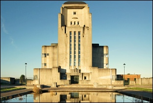
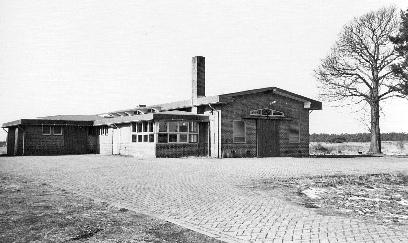
A recent view of the main building's front entrance and the cooling pond reveals that most of them remain unchanged, except for the absence of the tall aerial masts.
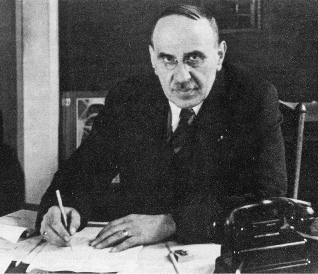
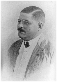
Two names are clearly marked in the history of Dutch radio: (on the right) Prof. Dr. Ir. N. Koomans (1879-1945) and (on the leftt) Dr. Ir. C.J. de Groot (1883-1927). With de Groot in the Dutch East Indies and Koomans in the motherland, PTT had two equally gifted and progressive leaders.
Dr. Ir. de Groot
In 1908, C.J. de Groot, a brilliant practical scientist, arrived in the Dutch East Indies appointed to a position at the Dutch East Indies PTT telegraph department. However, displaying interest and possessing sound knowledge in the field of radio, he was soon assigned to direct the installation of a chain of radio stations in the Dutch East Indies for local communication.
In late 1916, just before leaving Holland, de Groot visited the Telefunken Company, where he was offered a loan of a receiver to listen to the German radio station at Nauen. On his return trip to the Dutch East Indies, he made a detour to the USA and stayed two days at the Federal Telegraph Company, where he purchased a 100kW Poulsen arc.
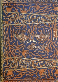
The experience with propagation between the stations, not well understood in those days, enabled de Groot to acquire a large amount of knowledge. This culminated in his famous PhD dissertation, ‘Radio-Telegrafie in de Tropen,’ [1] which he defended at the Delft Technical University during his leave in 1916.
One of his major (and historically best-known) statements in the dissertation was: ‘... direct radio communication between Holland and the Dutch East Indies without the use of intermediate stations is a political necessity and technically feasible...’.
[1] ‘Radio-Telegraphy in the Tropics’, the text of the dissertation printed in a limited edition, which is now a highly sought collector's item (right).
Mountain gorge aerial
Due to the war, adequate supplies of steel for building the planned tall aerial masts were not available. This led to Dr. de Groot's brilliant idea of using a mountain gorge as a suspension for an inverted 'L' aerial. A suitable site with the right orientation was quickly found in the Malabar area, very near Bandoeng (Java).
In November 1917, a temporary installation with an improvised aerial had been completed, operating at either 8000 or 16,000 meters. However, only one-sided communication would be possible as no suitable transmitter had yet been built in Holland. The initial power source was a makeshift arrangement comprising a spare generator from the Batavia Electrical Tramway Company, driven by a borrowed aircraft engine, limiting the power of the Federal arc to only 40 kW. From that time onward, regular signals were given on the hours of the day that were regarded as most suitable for communication to Europe. Messages were sent to Holland (i.e., the Dutch Naval Telegraph Service), but apparently, no suitable receiver seemed to be available, and none was received.
Naturally, the East Indies Government was not very pleased with this excuse, and in a Dutch East Indies paper of that time, exceedingly strong language ("treason") was used to describe this failure. According to reports from the Dutch East Indies government, the apparent refusal to listen for messages caused a delay of more than a year for the whole project.
Later in 1918, as still no firm steps had been taken in Holland to listen to the transmissions, a 3-valve receiver made in Dr. de Groot's East-Indies workshops was sent to Holland on an armoured cruiser of the Royal Dutch Navy.
During the journey, the Malabar transmitter was heard regularly, even at the furthest distance, the antipodes of Malabar, at the passage of the Panama Canal. Clear reception was recorded, which was a record distance for reception at the time.
A new generator, powered by a water turbine, had been installed by then to increase the power to about 200kW.
In 1919, upon the receiver's arrival in Holland, a receiving station at de Meent (in the centre of Holland) was built. It was a private venture, partly at the expense of the Dutch East Indies government. Almost instantly, Dr. de Groot's signals were heard. Only after a struggle of one and a half years and the intervention of the East Indies government was the first milestone achieved: a direct radio path, although one-sided. By that time, the war was over, and the cable blockade had been lifted.
East Indies, in order to establish improvised communication for Holland via the Nauen station. This measure was not really accepted by Dutch East Indies officials and the transmitter lay dormant at a Surabaya store. After a while, the transmitter was installed because instructions telegraphed from Holland insisted that it be installed and, if not, Germany threatened to stop the export of coal to Holland. [5]The site of the temporary Telefunken alternator, not very far from Malabar, was ready in late 1918. During the 1919 experiments, the station proved to be much weaker than the Malabar arc, primarily due to its lack of power and relatively small aerial. In December 1918, work on the Dutch transmitter station had already started after a suitable site was found in the centre of Holland, where the state owned a vast area of land unsuitable for agriculture or forestry. Consequently, the land was very cheap, and work started immediately.
Big arc
While the original Federal arc had been modified, allowing a power of about 200kW, and the provisional mountain aerial improved, communication was still considered not yet very reliable. Dr. de Groot decided to build a more powerful arc transmitter with a primary energy of approximately 2,400kW and additionally extend the mountain aerial. With this arrangement, he calculated that communication would be possible over a much longer part of the day.
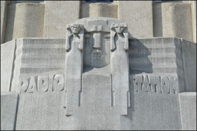
Above the entrance of the Kootwijk main building ('A') is an allegorical sculpture created by H.A. Van der Eynde. It depicts the transmitter station (resembling a large 'mouth') alongside two receiving stations represented by two listening figures


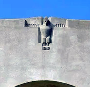
At the rear of the main building, a stylized eagle can be observed, created by H.A. Van der Eynde. With this sculpture, inspired by German expressionism, homage was paid to the alternator transmitter designers. Particularly after World War 2, this sentiment fell out of favour. Nowadays, many people explain the eagle as symbolizing the free flight of radio waves
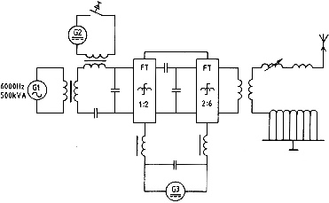
The Kootwijk transmitter, with the call sign 'PCG,' consisted of an alternator driven by an electric motor. It produced an AC current with (initially) a frequency of 6 kHz and a power of 500 kVA. Later, due to international agreements, the alternator frequency was reduced to 5.6 kHz, which was then tripled by a frequency transformer to an operating frequency of 16.8 kHz (17,850 meters), producing a power of 400 kW. The station had two alternators, one in operation and one as a spare.
Morse keying
Keying was performed by using a keying transformer connected in series with the secondary winding of the input transformer. While the Morse key connected to this keying transformer was pressed, the transformer core became saturated by the DC current from DC generator G2, which allowed the alternating current from alternator G1 to pass through. When the key was released and the transformer core was no longer saturated, it functioned as a choke with high impedance, preventing alternating current from passing through.
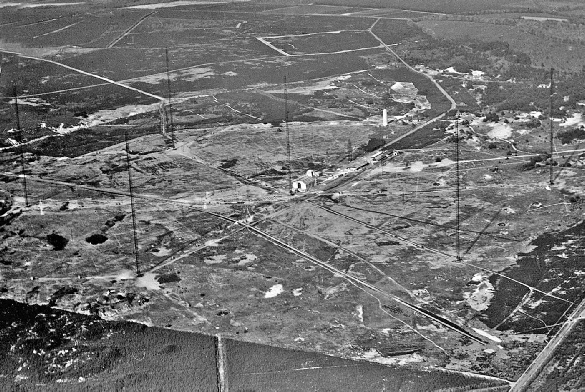
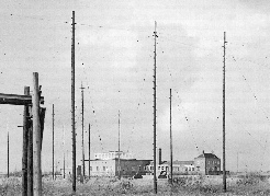
Photograph showing the 6 masts of the aerial taken in 1929 (above). A 7th mast was planned for future, but never realised. The design of the antenna was based on that of the Telefunken station in Nauen, with the shape of an umbrella. The pole was formed by a steel mast, from the top of which wires ran to five masts placed around the main mast.
Simplified circuit diagram of the Telefunken alternator.
FT (in the circuit diagram above) was a frequency transformer, of which in the initial phase of the station two were used in succession (1:2 and 2:6), so that the transmitter ultimately generated a high-frequency current of 36,000 Hertz, corresponding to a wavelength of 8,333 meters.
In this example we consider a 1:2 frequency transformer: when a sinusoidal alternating current is conducted through a winding on an iron core that is already magnetized to the saturation point by direct current, the half period with direct current causes little increase in the magnetic field, while the half period that works against the direct current will significantly weaken the magnetic field. The two iron cores C1 and C2 are magnetized to the saturation point by the direct current winding, each in the opposite direction in each of the two cores. The windings S1 and S2 are wound in opposite directions. If a sinusoidal alternating current is now sent through P1-P2, then in one half period, the magnetic field of core C1 will undergo a strong change and that of C2 will remain almost unchanged. In the next half period, the magnetic field of C2 changes and that of C1 does not. Consequently, S1 and S2 exhibit alternating complete periods, resulting in two periods for each complete period on the primary side (Pl-P2). The opposing windings of S1 and S2 caused the secondary cycles to synchronize, generating an almost sinusoidal alternating current with a doubled frequency. The secondary circuit S1-S2 was tuned by L/Cv to this doubled number of periods.
Frequency transformers

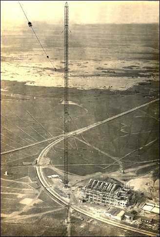
Photograph taken from one of the masts of the main building during construction (left). Note part of the large dug in earth mat.
A ‘Cathedral in the desert’
In the early 1920s, construction work on the station's main building began, and it took almost two years to complete. In the meantime, the six 212-meter-tall aerial masts and the huge umbrella-type aerial had been erected, and an extensive earth mat was dug in.
Luthmann's monumental station building, officially known as the 'A' building, had a specific style that was not an exact example of the 'Amsterdamse School.' However, it showcased other influences, such as expressionism. Some people compare the building to a Greek temple, while others describe it as a 'concrete cathedral.' A technical student from Sudan, who was posted to the station for a few weeks, spoke of a 'mosque.'
". . . another Dutch building where the classical conception determines the design, yet modern structure is expressed, is the Radio Station at Kootwijk, designed by J. M. Luthmann. It is not difficult to see this as a transformed Greek temple where, instead of a comparatively heavy stone construction, it has a lightness of aspect, especially in the treatment of windows, made possible by steel..." – A. Whittick, 1974 [8]
A great many of the past and present visitors to the station are deeply impressed, undoubtedly by the mystic atmosphere of the huge building situated in a remote, uninhabited area. When approaching the station from the main road, the station's main building can be seen at the end of a long, straight lane. Upon entering the main entrance, visitors can still feel the atmosphere of the past, emphasized by the recent restoration of large parts of the interior, which were painted over in the 1960s, to their original condition. A professor of the architecture at Delft University of Technology invariably took his students every year to the Kootwijk station to show them the remarkable architectural details.
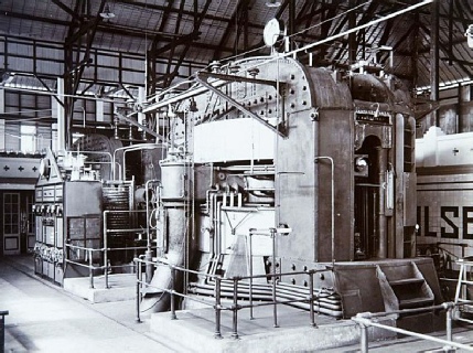
Telefunken alternator
In the early days of radio, VLF (Very Low Frequencies) were considered the most suitable for long-distance communication. Technically, only a few systems allowed the generation of suitable RF power. The Telefunken transmitter installed at Kootwijk, included an Alexanderson-type alternator with a saturated core transformer frequency multiplier, providing a limited number of frequency choices (3x, 4x, or 6x the frequency of the alternator). The output power of the alternator was about 400 kW, and the RF current at the feeding point of the aerial was approximately 350 A. The frequency of the alternator was initially 6 kHz, resulting in operating frequencies of 36 kHz (8333 meters), 24 kHz (12,500 meters), or 18 kHz (16,666 meters). Later, due to international agreements, it was necessary to move to 16.8 kHz/17,800 meters or alternatively 11.2 kHz/26,700 meters at a generator frequency of 5.6 kHz. In practice, the alternator transmitter operated at 16.8 kHz for most of its life with the call-sign ‘PCG.’ Alternator transmitters were reliable and easy to maintain, although they were more expensive and less flexible in frequency coverage compared to arc transmitters. The frequency stability of the Telefunken alternator was initially rather poor. In 1925, the PTT radio laboratories designed an electronic device that considerably increased stability. By then, the PTT radio laboratories had accomplished other improvements of the alternator transmitter, such as a new aerial variometer with a sliding construction.
Obsolete
On January 18, 1923, the first operational two-way contact with the Dutch East Indies was established on a frequency of 36 kHz (8,333 meters). A few months later, on May 5th, the radio link was inaugurated, and on May 7th, it was opened for public use.
Operating times were, as anticipated, only when the radio path was in the dark (Holland approximately from 19:00 to 24:00 hours, East Indies approximately from 02:00 to 07:00 hours, both local time). In late 1924, in an attempt to extend the rather
The radio link 'Holland to Dutch Indies' was inaugurated on 5 May 1923 with the 'PCG' transmitter in Kootwijk and receiving station at Sambeek. In the Dutch Indies, it was received at Tjangkring, with the transmitter located in Malabar.
Part 2: A new era: Short Wave
Short wave
In December 1921, American amateurs bridged the Atlantic Ocean using short waves and very low power. The first two-way short-wave amateur contact between Holland (call-sign ‘PCII’) and the USA (‘2AGB’) was established on December 23, 1923. It is interesting to note that the original and complete PCII transmitter used during these contacts is in the custody of ‘Het Nederlandse PTT Museum’ (now ‘Beeld en Geluid’) [12].
Although contemporary professionals were very skeptical and warned about over-optimism, work on a proposed short-wave link started in 1924. Once again, the Dutch East Indies were ahead, and on February 17, 1925, the shortwave transmitter ‘ANE,’ located in Bandung, Java, was received with a very strong signal in Holland on a wavelength of 95 meters.
Only a few months later, Dr. Ir. Koomans completed the first short-wave transmitter located at the radio laboratory in The Hague. It was an instant success. On August 17, 1925, only about two years after the inauguration of the alternator transmitter, this provisional transmitter (call-sign ‘PCMM’) became operational, keyed from the radio terminal in Amsterdam. It was soon followed by a second, more powerful transmitter ('PCLL').
In early 1926, four transmitters of the 'PCLL' type were hastily installed in the 'B' building at Kootwijk radio. The frequencies of the four transmitters were divided into wavelengths between 16 and 51 meters. This allowed for a simple arrangement to switch from one frequency to another, providing a nearly 24-hour radio link. For just a few hours during the night when conditions were unfavourable, the alternator transmitter ‘PCG’ would provide relief. This was only the beginning of the very tempestuous development of Kootwijk radio's short-wave service, which continued to the close of the station. The simple vertical quarter-wave aerials were soon replaced by more complex beams. Dr. Ir. Koomans made significant contributions in this field and obtained several patents, including one for the 'Koomans array.'
In the late 1920’s, a new short-wave site was constructed just a few kilometres away from the alternator transmitter site. This shift left the obscure 'B' building for a more spacious complex, comprised of buildings 'C,' 'D,' 'E,' and a control room. This new setup allowed for the installation of large beam aerials. In 1928, a reliable 24-hour radio link to the Dutch East Indies on shortwave was achieved, thanks to the improvements made at both stations.
Threat of Privatisation
It is little known that the shortwave service saved the alternator link from being discontinued due to high operating losses. In 1923 and 1924, it was found that the alternator transmitter service was losing money due to high operating costs and reduced interest in sending expensive telegrams through a service that was only available for a limited number of hours a day. In 1925, an independent commission recommended the privatisation of all fixed service radio links. However, due to the positive results of the short-wave service, which could operate almost throughout the day at a fraction of the cost of the alternator transmitter, and because the radio laboratories were able to produce reliable short-wave transmitters at only 1/15th of the price of a commercial manufacturer, the board of ministers decided to maintain the fixed service at the PTT.
In addition, Kootwijk radio housed a number of short-
Single sideband telephony with suppressed carrier
In 1927, the first experimental (semi-public) telephony link to the Dutch East Indies was opened. On February 28, 1928, a public radio-telephony link to the Dutch East Indies, the longest direct radio-telephone link in those days, was inaugurated. In the subsequent years, many improvements were made, including extensive aerial arrays, crystal control, and, most importantly, the introduction of single-sideband with suppressed carrier. Its application on shortwave was a world first in 1933. Only one year later, all the Kootwijk transmitters used for the East Indies had been converted to this system. In 1935, Dr. Koomans and his team increased the capacity by combining two telephone circuits and a telegraph circuit over one transmitter. In 1937, experiments showed that this capacity could be increased to four telephone circuits plus a number of telegraph channels over one single-sideband link. In the subsequent years, this new modulation technique was continuously developed and perfected, a process that continued beyond the Second World War.
Radio for the Nazi’s
On May 11, 1940, the second day of the German invasion of Holland, the Kootwijk station was occupied by the Germans. It was taken over and soon used for military purposes. During the war, the VLF alternator transmitter 'PCG' was primarily used to transmit coded messages to submerged U-boats in the North Sea and parts of the Atlantic, with a range of about 1,000 miles. Many of these messages were decoded by the British, who cracked the Enigma code (codename 'Ultra'). The fact that the code had been cracked might explain the lack of any large-scale air attacks on the station during the war. The Allies gained more information when the station was operational. It was only occasionally attacked by low-level, long-range aircraft of the RAF, leaving a few 2cm holes in the rails of the crane in the main building hall,
In retrospect
It is characteristic that between 1919 and 1940, the development and operation of fixed-service radio took place exclusively within the laboratory. Nevertheless, this laboratory development wasn't unexpected, considering that Professor Dr. Ir. Koomans, as the director, had direct oversight of both the radio laboratory in The Hague and the Kootwijk and Nora radio stations.
Despite British air attacks, German ‘spreng-kommandos’ and the passage of time, Luthman's main station building remains as robust as ever. With its unique design, it has been added to the Dutch list of National Monuments, ensuring the preservation of the building and protecting it from destruction. Looking back on the years, it is easy to identify a number of apparent failures. However, considering its reasonable stability and extreme reliability, the choice of the Telefunken alternator was not one of the worst failures for Holland. Unlike a powerful arc transmitter with its harmonics or a synchronized disk, which could have been installed by the Marconi Company, the alternator was able to withstand the test of time, remaining in operation until 1945.
In 1918, at the time of purchasing the alternator, the rapid advancements in valve technology and the discoveries of the possibilities of short waves could not have been accurately foreseen. It is noteworthy that in 1916, Telefunken provided Dr. Ir. de Groot with a modern receiver for that era. However, when the Dutch East Indies urgently requested Holland to listen to its improvised arc transmitter in 1917, it appears that no receiver was available. The story goes that Telefunken refused to lend a receiver unless they were contracted to build both stations [5]. Eventually, it turned out that the Telefunken receivers were unsuitable, leading Dr. de Groot to construct his own receiver in early 1918. Shortly thereafter, Dr. Ir. Koomans replaced his Telefunken receiver with a circuit invented by Armstrong [15].
Kootwijk radio in the final period
The fixed service (point-to-point) radio communication at Kootwijk radio ceased in 1974 [6], being superseded (after 1956) by modern transatlantic cables and in 1973 by satellite communication after the opening of the PTT satellite ground station at Burum. The importance of mobile (maritime) traffic increased considerably, despite the boom in satellite communication. Kootwijk radio was then primarily used for long-distance (worldwide) maritime traffic, controlled by the Dutch coastal station Scheveningen Radio. At the end of 1998, this era was also coming to an end with the closure of Scheveningen Radio.
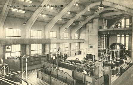
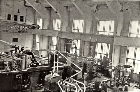
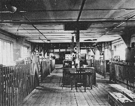
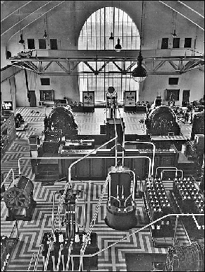
A view of the main hall taken after 1927 after the Lorenz long wave transmitter ‘PEM’ had been installed (background left). (This is a scan of one in a series of postcards of the station).
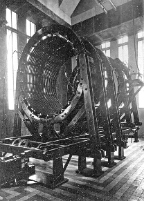
In this photo, one of the alternators (right), driven by a motor (left). Note the round object on the front of the motor, which contained a part of the later-added electronic frequency governor.
Part 3: The postwar era.
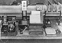
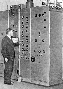
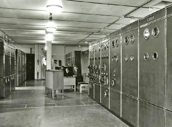
Shown on the right was the operating position of the 'PCG' alternator transmitter (operating on 17,800m) at the Amsterdam radio terminal. Telegrams were initially typed by means of the keyboard of a perforator (centre), which provided a tape that was fed through a high-speed Morse transmitter (left).
Note an ordinary hand-speed Morse key (right), which was available as a standby
The original Telefunken aerial loading coil (left) was soon replaced by a variometer and aerial inductance designed by the Dutch PTT (right). This continuously tunable system, operated by a motor controlled from the control deck, proved to be a significant improvement
limited traffic hours of the Holland-Malabar link, traffic was rerouted by using the Malabar-San Francisco radio route, from there by cable to New York, and finally by the New York-Kootwijk radio link. However, the advent of high-power valves and the discovery of the possibilities of shortwave made the alternator obsolescent. By late 1920s, the ‘PCG’ alternator transmitter was only used for transmissions to New York (European traffic had already been taken over by valve transmitters) and as a standby for the Dutch East Indies link, in case the shortwave link would fail.

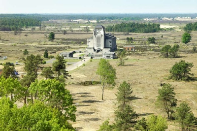
A photo taken from the same spot as the Radio Kootwijk 'A' building shows it as it is today, after most buildings and all aerials have been removed. The 'A' building is now owned by the Dutch State Forest Commission and is rented out for events.
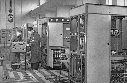
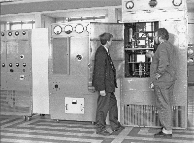
"PTT colleague Station Martin Nieuwenhuizen (on the right) showed the author some details of the driver unit of the once-famous Philips ‘PCJ’ shortwave broadcast transmitter, which at that time had found a temporary resting place in the main hall of Building ‘A’. (This photo was believed to have been taken in 1989)."
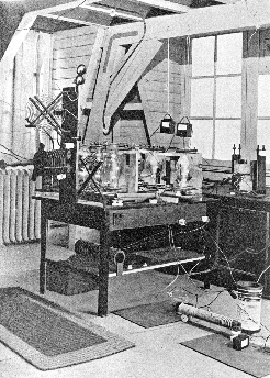
The first Dutch shortwave trans-mitter, with the call-sign 'PCMM,' was designed in early 1925 by the PTT Radio Lab in a very short time, in order to respond to the transmissions of Dr. de Groot's 'ANE' shortwave transmitter in the former Dutch East Indies. Please note the provisional construction on a lab workbench in the attic of the building. The transmitter's power was limited to 2kW because air-cooled valves were used. A second provisional transmitter with the call-sign 'PCLL' became operational two months later, featuring a water-cooled valve and allowing for more power. This design served as a model for four shortwave transmitters in the 'B' building at Kootwijk radio.
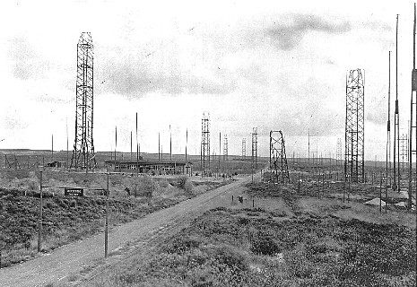
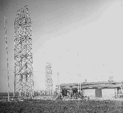
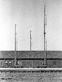
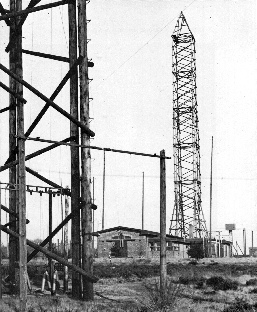
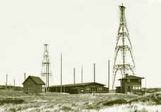
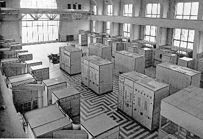
In 1926, at the beginning of the shortwave era, Kootwijk radio's 'B' building housed the four initial transmitters. At that time, the aerials were simple vertical quarter-wave radiators (only three are shown in the photo on the right). A few years later, a completely new shortwave site was constructed, comprising three transmitter buildings known as 'C,' 'D,' and 'E,' along with a control room (which later became known as building 'F').
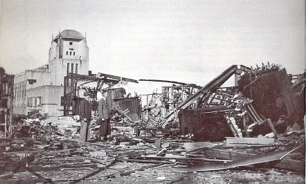
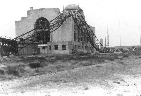
This was left of the 'A' building when the Germans retreated from Kootwijk radio and senselessly destroyed what remained (above and below). Most of the technical equipment had already been dismantled and transported to Germany.
These were the remains of the 1,875-meter long wave broadcast transmitter located in building 'B' (above). A new transmitter was constructed and became operational in 1947, remaining in use until the 1950s. However, during a frequency conference, it was decided that this frequency needed to be relocated.
In 1940, a 3kW transmitter under construction, hidden from the Germans, was rebuilt and commissioned for traffic to North America in October 1945 with two speech channels using a pre-modulator that had been hidden from the Germans at the PTT Radio Laboratorium (left).
Malabar
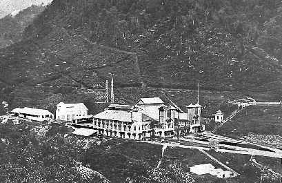
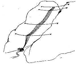
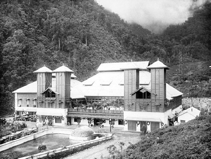
A view of the Malabar station central building (left) and part of the mountain gorge on which the aerial was suspended (drawing right).
The large aerial consisted of seven aerial wires hung on steel cables by means of two insulators in series. The highest point of support was situated about 900m above the station, and the total length of the aerial wires was about 1800m. The effective height varied between 320 and 480m.
‘B’ building with the initial shortwave transmitters (above and below).
View of the front of the central building of the Malabar transmitting station taken at the inauguration on May 5, 1923. Note the cooling pond in front of the building.
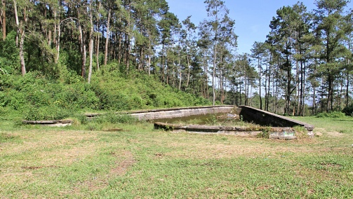
The Malabar station was partly damaged in WW2 and was demolished and set on fire in 1947. It was never rebuilt. Today, just a few foundations can be seen. Shown here are the remains of the cooling pond. More photos on https://www.flickr.com/photos/tomsez/
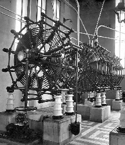
A 400kW Telefunken alternator transmitter was also installed at the Malabar station (as shown above). Similarities in construction with the Kootwijk transmitter can be noted. As shown in this photo, there was only one alternator, even though space was apparently reserved for a second.
While not within the scope of the Kootwijk radio station, in this update of the original article 33 years later, it made sense to give more attention and tribute to the work of Dr. de Groot at Malabar. His large arc transmitter, often referred to as the '3,000kW arc,' typically operated at an input of 1,600kW and occasionally at 2,400kW.
Wooden Aerial towers supported the Koomans arrays near building ‘C’.
An overall view of the shortwave site, as it appeared from the North, featured building 'C' on the left and buildings 'D' and 'E' in the background (above).
The 2,400kW scaled-up Poulsen ‘big arc’ transmitter.
The ‘E’ building in about 1989.
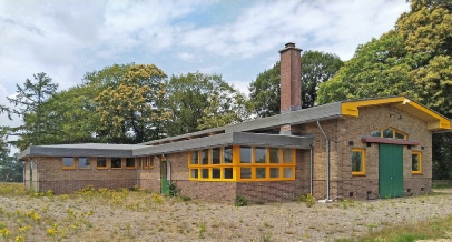
The 'E' building, renovated, now houses a team-building company known as the 'Dream Factory' today.
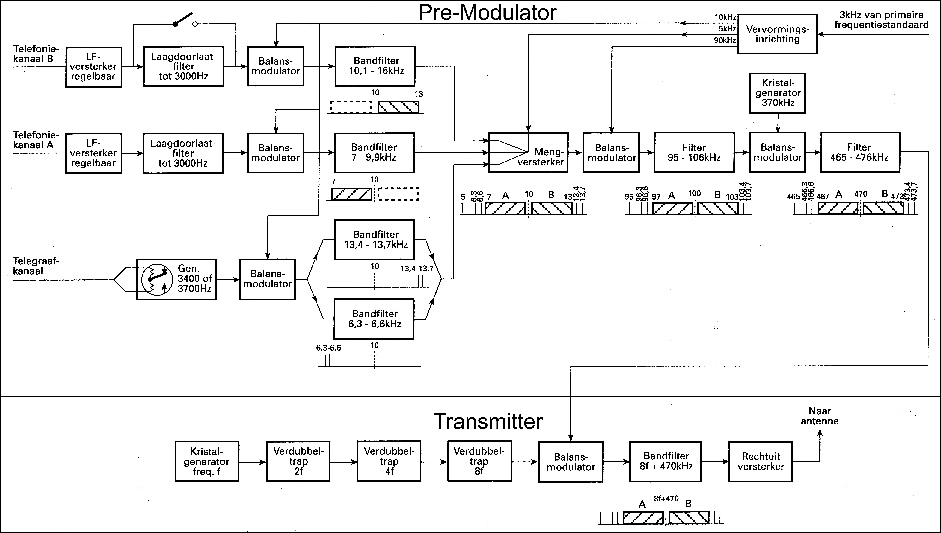
In the block diagram below, one of the transmitters with a pre-modulator is depicted. This transmitter was set up to handle two telephone channels, A and B, as well as a dual-tone telegraph channel (situation around 1934-35).
The pre-modulators were located in a separate building, within a room shielded against the strong electromagnetic radiation emitted by the transmitters (the later 'F' building). This was where the telephone and telegraph signals to be transmitted were received. Additionally, a control receiver was used to verify the accuracy of the transmission.
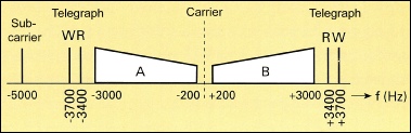
The levels of telephone channels A and B were adjusted to their desired values in the pre-modulator through amplification. The signal from each channel was then passed through a low-pass filter with a cutoff frequency of 3000 Hz and fed into a balanced modulator, where amplitude modulation occurred on an auxiliary carrier wave with a frequency of 10 kHz.
Through bandpass filtering (7-9.9 kHz for the A channel and 10.1-16 kHz for the B channel), the lower sideband ended up in the A channel, and the upper sideband in the B channel. When a broader spectrum was needed for transmitting music, the low-pass filter in the B channel was short-circuited, and the telegraph channel was not used. The telegraph signal was converted into a dual-tone signal: a rest tone of 3400 Hz and a working tone of 3700 Hz. In the subsequent balanced modulator, they were also modulated onto an auxiliary carrier wave of 10 kHz. Two parallel-connected bandpass filters separated the upper and lower sidebands from the modulation. Both sidebands were transmitted to reduce sensitivity to fading.
Apart from separating the signals, the four bandpass filters also removed the residual carrier wave because it was not completely eliminated in the balanced modulators. The output signals from the filters were combined with a 5 kHz signal in a mixer-amplifier. The 5-kilohertz signal was used for automatic frequency correction of the receiver at the other side of the link. The signal band was then transformed into the 465-476 kHz range in two modulation steps and transported via a cable to
Location of the individual speech channels and the double-tone telegraph channel in relation to the suppressed carrier.
one of the transmitters in the transmitter building.
The frequencies of the auxiliary carrier waves (5, 10, and 90 kHz) were generated on-site from a 3-kilohertz signal originating from the primary frequency standard of the Radio Laboratory.
Within the transmitter, the carrier frequency was initially increased in three steps to eight times the frequency of the crystal oscillator. Subsequently, the output signal from the pre-modulator was modulated onto the carrier wave using a balanced modulator. The upper sideband was then filtered from the modulated signal, which was subsequently amplified by a linear amplifier to reach the nominal output power, after which the signal was fed to the aerial.
In practice, complete suppression of the carrier wave proved necessary because even a slight presence of it allowed intelligible reception with a regular broadcast receiver. Initially, secrecy in radiotelephony was a significant concern. When the user had high demands, the PTT technical department applied scrambler equipment. On the transmission side, the speech band was first divided into several pieces, which were then mixed in a specific manner. On the receiving side, they were placed back in the correct positions within the band. During the rapid and continuous development of the station, the pre-modulator was later extended to accommodate four speech channels and four telegraph channels.
which today serve as sinister remnants of a dark period. The 1,875m broadcast transmitter, located in the 'B' building with its aerial slung to one of the ‘PCG’ aerial masts, was used for propaganda and relaying Radio Bremen, known as 'Sender Friesland.' It is interesting to note that the single-sideband receivers of the reception station at Noordwijk radio (NORA) were extensively used by the Germans to intercept the secret (scrambled) high-command radio telephone link between England and the USA.Much of the Kootwijk station was senselessly destroyed in April 1945 by the retreating Germans. The six aerial masts were blown down, and the alternator transmitter ‘PCG’ and 1,875m broadcast transmitter were destroyed by explosive charges. In 1944, most of the shortwave transmitters had already been removed and transported to Germany.
Condensed details of a Kootwijk short wave transmitter and pre-modulator
Block diagram of the initial (1934) pre-modulator and transmitter.
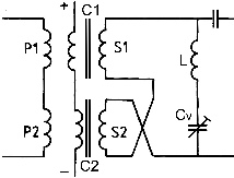
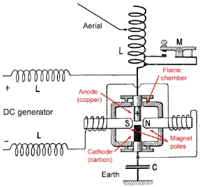
The arc transmitter, also known as the Poulsen arc after Danish engineer Valdemar Poulsen, who invented it in 1903, was a type of spark transmitter used in early wireless telegraphy. It used an electric arc to convert direct current electricity into radio frequency alternating current. It served as a radio transmitter from 1903 until the 1920s when it was replaced by valve transmitters. One of the first transmitters that could generate continuous sinusoidal waves, it was among the first technologies used to transmit sound (amplitude modulation) by radio. One of its main advantages was the flexibility in frequency coverage, which was the primary reason for Dr. Dr. Groot to choose this system, along with the fact that the power could be increased by scaling up the original design.
Since the arc took some time to strike and operate in a stable fashion, normal on-off keying could not be used. Instead, a form of frequency-shift keying was employed. In this compensation-wave method, the arc operated continuously, and the key altered the frequency of the arc by one to five percent. The signal at the unwanted frequency was called the compensation wave.
In arc transmitters up to 70 kW, the key typically shorted out a few turns in the antenna coil. For larger arcs, the arc output was transformer-coupled to the antenna inductor, and the key shorted out a few bottom turns of the grounded secondary. Therefore, the ‘mark’ (key closed) was sent at one frequency, and the ‘space’ (key open) at another frequency. If these frequencies were far enough apart, and the receiving station's receiver had adequate selectivity, the receiving station would hear standard CW when tuned to the "mark" frequency. This ‘compensation wave’ method used extra bandwidth.
A simplified electrical circuit diagram of a Poulsen arc transmitter is shown here. Not depicted are the mechanical attributes, such as the injection of alcohol (or petroleum) into the flame chamber to create a hydrogen atmosphere, the water cooling of the copper anode, and the rotating/adjustment mechanisms of the carbon cathode. Pure hydrogen was used in the 2,400kW arc at Malabar [25].

The Poulsen arc transmitter
Arc transmitters were also rich in harmonics and transmitted not only on the two intended frequencies but also on the harmonics of those frequencies. Around 1921, the Preliminary International Communications Conference prohibited the compensation wave method because it caused too much interference. The need to emit signals at two different frequencies was eliminated by the development of the so-called 'uni-wave' methods.
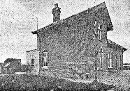
Most of Kootwijk radio's original buildings remained intact in the 1990s, although many were no longer used for their original purposes. The main 'A' building had undergone few alterations, and the entrance hall had recently been restored to its original state. Other structures designed by Luthmann, including the water tower, a former hotel, and station personnel houses, remained unchanged. During the 1970s [6], most of the former short-wave buildings from the 1920s had been re-purposed as PTT offices for various departments, such as the Aerial Construction Department and the Microwave Transmission Group. These departments gradually relocated to other sites following the closure of the maritime service in 1998.
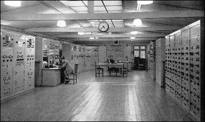
Control room in the F building (1952).
Maintenance of transmitters in building ‘A’ (1952).
Two of several wooden aerial towers supported the 'Koomans' array aerials. Building 'D' was located on the right.
A new version of the pre-modulator was later developed by the PTT Radio lab, allowing the transmission of four telephone and two telegraph channels over a single radio link. At this stage, the suppressed carrier frequency of this low-level output to a transmitter was changed from 470 kHz (as shown here) to 1 MHz [19].
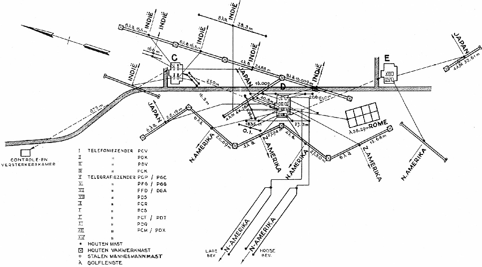
This map showed the Kootwijk shortwave radio facility situation around 1936/37. It displayed buildings 'C,' 'D,' and 'E' with Koomans arrays, the control building 'F,' and two Beverage aerials at the bottom of the drawing, both directed toward North America.

Acknowledgements:
The author would like to express gratitude to his KPN Telecom colleague, Martin Nieuwenhuizen, the last station manager of Kootwijk Radio, not only for about 15 years of pleasant professional co-operation, but also Martin's enthusiasm for the history of the station that greatly inspired the preparation of this article.
Posthumous thanks are extended to Kaye Weedon for encouraging the author to further study the work of Dr. Ir. de Groot and his contemporaries. Special thanks are due to the the (former) photographic section of the PTT Museum in The Hague, Holland, (now ‘Beeld en Geluid’) for providing a significant portion of the photographs.

wave transmitters were used for Scheveningen Radio, the Dutch coastal station for maritime services. This was due to the limited space at Scheveningen radio's transmitting site, which primarily served MF transmitters for traffic up to 1000 km. inn 1927, the first shortwave transmitter for maritime service was installed at Kootwijk, and this service gradually expanded to handle a large proportion of the station's traffic. In addition to the systems described here, there were numerous fixed-service long-distance short-wave links to many countries, including traffic on long wave to various European countries.
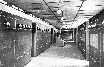
Transmitters installed in the ‘C’ building (below).
There, Dr de Groot received instructions on how to increase the power of this type of arc transmitter, which would enable him to make direct contact with the Honolulu radio station and, from there, transmit signals to Holland through neutral USA. However, during de Groot's absence, it was shown that powerful European stations such as Nauen, Eilvese, Bordeaux, and Carnarvon were regularly received in the Dutch East Indies. This gave de Groot confidence in his initial plan of establishing direct radio communication with Holland. His ideas were welcomed and supported by the Dutch Indies Government, which provided him with almost unlimited funding. By the time the Federal Telegraph Company arc transmitter arrived in August 1917, significant progress had already been made on the transmitting station site.
Kootwijk and Meyendel became firmly connected to Amsterdam, and a favourable circumstance arose: the entire service operation was now under one management. Concentrating on a significant centre like Amsterdam made sense because most telegrams for the Dutch East Indies originated from here. Furthermore, Amsterdam was connected to every place of importance through a direct telegraph line.
At the opening of the Kootwijk-Dutch East Indies radio link, the situation was such that the transmission and reception services were conducted separately. Kootwijk served as the transmitting station, while Sambeek served as the receiving station, with telegraphers stationed at both locations. If a word was not received correctly in Sambeek, the telegraphers there had the ability to interrupt the transmission from Kootwijk to inquire about the word. It was, therefore, not surprising that this situation was not maintained. Already on August 4, 1924, the service was centralised in the radio terminal in Amsterdam. Since Sambeek was too far from Amsterdam for an efficient direct cable connection, the receiving station was relocated to Meyendel.
His two significant achievements were the conception and construction of the first and second mountain gorge aerials at Malabar, along with the immense, scaled-up Poulsen arc transmitter, were undertaken under challenging conditions in the tropical East Indies. Dr. de Groot's decision to use an arc transmitter was primarily based on its wide frequency coverage and the potential for power up-scaling from the original design.
Radio terminal in Amsterdam
Long wave broadcast transmitter
In 1933, a provisional AM broadcast transmitter, operating on a wavelength of 1,875m, was installed in the 'B' building after all shortwave activities had been transferred to a new location. It was replaced in July 1935 by a more powerful 120kW transmitter. The aerial for this transmitter was also supported by two masts of the aerial of the alternator transmitter. This broadcast transmitter was used for German propaganda during the occupation in 1940-45 and was known as 'Sender Friesland'
Partial view of the 120kW long wave broadcast transmitter in the ‘B’ building.

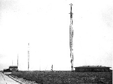
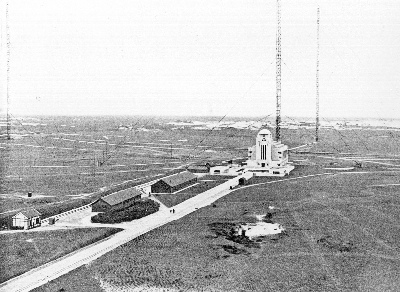
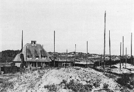
Kootwijk Radio, photographed in 1923 from the top of the water tower, stood in the middle of an infertile, desert-like plain. Five masts were arranged at the corners of a hexahedron, with a sixth mast (located near the main 'A' building) at the centre. Copper wires connected the masts, forming an aerial in the shape of an umbrella, a configuration commonly used by Telefunken at the time. Only three of the massive 212m masts are visible in this photo. Take note of the 'B' building, situated closest to the main building, which initially housed the station's shortwave transmitters.
Situation of the main hall in about 1952.
The main hall, as seen from the opposite side, showed both alternators, the control deck, and the frequency transformer (left).
A small part of the Philips long wave transmitter with the call-sign 'PEW' was visible on the left
In late 1919, as part of the Telefunken contract, a receiving station was built under the supervision of Dr. Ir. Koomans (of whom we will hear more later) in Sambeek, in the southeast of Holland, about 70km away from Kootwijk.
The completion of the Sambeek receiving station initiated a friendly competition between the Dutch PTT station and the ‘de Meent’ station of the Dutch Indies government.[7] However, as the Sambeek station was gradually improved and modernized, the reception station of ‘de Meent’ could not keep pace and was forced to close. Nevertheless, its necessity had been proven by then. Telegrams received from Dr. de Groot's arc or the 400kW Telefunken alternator (which had been installed by then, and using part of Dr. de Groot's Mountain gorge aerial) were further dispatched by line. In August 1924, the Sambeek station was transferred to Meyendel near The Hague, located much closer to the radio office in Amsterdam and providing easier access, and consequently, closer contacts with the PTT radio laboratory in The Hague.
However, the rapid developments of shortwave and expansion of long wave traffic with European countries made further extension necessary. As a temporary measure in 1926, a receiving station at ‘het Schouw’ (near Amsterdam) was opened, which soon handled most of the transatlantic traffic. This awkward situation continued until the opening of Noordwijk radio (Nora) in 1928 on the North Sea coast, where it remained until 1950, after a new station had been opened at Nederhorst den Berg radio (Nera).
In the period 1927-1930, three long-wave telegraphy valve transmitters were added in the hall of building ‘A’ for traffic with European stations. The aerials of these transmitters were suspended between the masts of the 'PCG' alternator transmitter.
These transmitters were as follows:
- Call sign ‘PEM,’ operating on 2975m, was built by Lorenz in 1927 with a power of 20kW.
- Call sign ‘PER,’ operating on 3350m, was constructed by PTT in 1927 with a power of 20kW.
- Call sign ‘PEW,’ operating on 4637m, was built by Philips in 1930 with a power of 40kW.
Postwar period
After the liberation of Holland in May 1945, many of the Radio Kootwijk buildings were damaged, and all the technical equipment had to be entirely rebuilt. A single 3kW transmitter that had been under construction and nearly completed was hurriedly disassembled in May 1940 and hidden from the Germans during the war. This transmitter was reassembled first, and in October 1945, it was put into operation for traffic to New York. Most of the shortwave transmitters were later found in Germany on a railway track in very bad condition. In 1947, two 40kW transmitters were reconditioned and put into operation again.
In 1946, fragments of the demolished masts were used to erect two 200-meter masts that carried the aerials for two long-wave transmitters for European traffic. As the days of long waves were numbered, they were only used until the mid-1950s. Because they were no longer in use, one of the two huge masts was demolished in 1966, and the other in 1980.
During the early post-war years, Kootwijk radio saw a rapid expansion in the number of transmitters, reaching its highest number in the mid-1950s. In 1954, the station had about 53 shortwave transmitters for global communication and two long-wave transmitters for European traffic.
Old meets old
In the 1980s, the pre-war shortwave broadcast transmitter 'PCJ,' which gained fame for its historical worldwide broadcasts in the late 1920s and 1930s, was relocated from Philips in Eindhoven to Kootwijk. It found a worthy but temporary place in the hall of the 'A' building, at the same spot where the 'PCG' alternator transmitter had operated for many years. After the closure of Kootwijk Radio, the 'PCJ' transmitter returned to Eindhoven in 2001 and is now part of the collection of the 'Stichting Philips Historische Producten'.
Epilogue
This final part of the trilogy, 'Mobile Radio/Radio-Paging/Fixed Service Radio in the Netherlands,' provides a small yet fascinating glimpse into the role of the Dutch PTT in the field of radio communication.
In this 30-years-later version, technical details are highlighted, along with other interesting facts, including seemingly minor details that are not commonly known. The main transmitting hall, which dates back to 1923, is now in use as an events location, and it has found a worthy place in Dutch society.
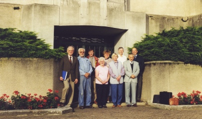
You may wonder what the WftW website has to do with Radio Kootwijk. It served as the location for a small conference held on September 9 and 10, 1998, which aimed to discuss the future writing of a book on agents and SOE communication titled 'Wireless for the Warrior, Volume 4: Clandestine Radio.' The conference took place in one of the offices in Building 'A.' Originally planned in the early 1990s, it was postponed due to the unexpected death of John Brown, the designer of the iconic 'B2' WW2 agents' radio set, and was only held many years later. Rudolf Staritz can be seen as the second person from the left in the accompanying image.
Kootwijk Radio today (2023)
All remaining equipment, including the aerials, were removed from 2001 onwards. KPN Telecom sold the grounds and buildings in 2003 to the Dutch State, after which most of the grounds went to the Dutch State Forest Commission (Staatsbosbeheer). The buildings were transferred in 2009 into the custody of this organisation.
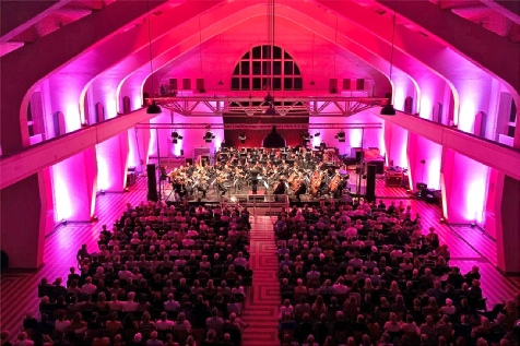
Among the various commercial activities organised on the former Radio Kootwijk grounds, including company events, weddings, dinners, and conferences, concerts held in the 'A' building are very popular.

