(Louis Meulstee’s web site)
 Home
Return
ASR 1
ASR 2
ASR 3
ASR 4
Home
Return
ASR 1
ASR 2
ASR 3
ASR 4


Gibson Girl part 1. Air-Sea Rescue: Long wave and short wave
Introduction
During my time in the Service I had been fascinated by the peculiar shape of the US manufactured emergency transmitter type AN/CRT-3, affectionately named 'Gibson Girl'. I later learned that its primary design came from war-time Germany. Emergency transmitters enabled ditched air crews to transmit an emergency call on a frequency of 500 kHz (and in some models also on short wave), used by international radio alarm
Notsender NS2
The complete set, known as NSG2, for Not Sende Gerät 2, (Emergency Transmitter Equipment, type 2) consisted of two parts: the NS2 transmitter container and the accessories container, usually stowed loose in the aircraft and attached to a rubber dingy. Both containers were made of a light alloy. The accessories container held a kite, two balloons with filling tubes, two hydrogen generators and an instruction handbook, together weighing 29 lb. Click here for the circuit diagram.
The range over sea was given as approximately 200 miles. Power was derived from a hand generator, with the handle fitted on top of the transmitter case. The NS2 had a quite unique ergonomic shape. When used it was held between the operator's legs, giving the impression of grinding coffee in an old fashioned hand grinder. Since no batteries were needed the set could remain in storage for long periods of time without service or attention and when required it was ready for immediate service.
Automatic SOS Code
When turning the handle of the hand generator (approximately 2 revolutions per second), automatic keying of SOS and long dashes on MCW or CW were transmitted. A moulded cam, mounted on a camshaft, carried a series of depressions operated the keying contacts. In addition, a hand key could be used to transmit other messages such as instructions to aircraft flying over. The simplicity of operation and automatic transmission permitted the set to be operated by any member of the crew.
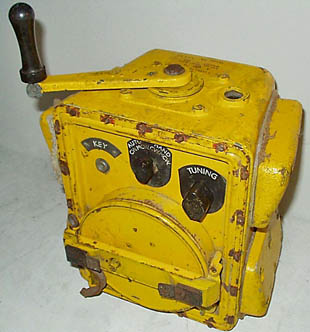
NS2A Notsender 2a (Emergency Transmitter, type 2a) was manufactured by Philips, had a similar performance as the NS2, but was mechanically simplified. It had not the ergonomic shape of its predecessor, although it might be possible that pads (similar to the British T-1333) were fitted on both sides of the case. The generator handle was fitted on the top of the transmitter, on the picture (left) shown protected by a cap.
Both NS2 and NS2a operated on the international distress frequency of 500 kHz (600 metres). To obtain a good range it needed a long-wire aerial of reasonable length. This was normally provided by attaching the aerial, 260 feet of stainless steel wire, to a box kite. It was reeled out by a unit mounted on the front panel of the set.
The earth, consisting of 10 feet of stainless steel wire terminated to a sinker, was lowered over the side of the dinghy into the sea. When lack of wind (less than 13 mph) did not permit the use of a kite, a 3ft balloon was inflated by a hydrogen generator, a tin can with a separate inflation tube. When opened, hydrogen was generated by chemical solid (lithium hydride or calcium hydride) coming into contact with water. An insulated grip on the inflation tube provided protection to the hand as considerable heat was generated during this process.
Crystal Control
The NS2 and NS2a transmitters were crystal controlled, giving excellent stability in extremes of temperature. The RF output was specified as 8 watts CW and 6 watts MCW. Two valves were employed: an AL5N as oscillator-RF output valve and RE134 as audio oscillator-modulator. An aerial tuning circuit, provided with a neon tuning indicator, compensated for variations in aerial length and capacity.
Notsender NS1
The NS2 and NS2a were not the first Luftwaffe dinghy transmitters, as prior World War 2 (and recorded to be used also during the war) emergency transmitter set type NSG1 had been developed. The transmitter part of this set, Notsender NS1 was originally part of a Lufthansa 'Kleinstation' developed in the mid 1930s as an aircraft station, but later exclusively used for emergency communications. The NSG1 was really a makeshift solution for long range aircraft, to be replaced ultimately by NSG2. It operated on a frequency of 500 kHz and was powered by dry HT batteries and an LT accumulator. Transmission (CW only) was automatic SOS, followed by a long dash, operated by a small motor, or alternatively hand keyed Morse.
The NS1 transmitter was mounted in a bulky weatherproof case painted bright yellow and weighed 50 lb. The aerial consisted of five sections of aluminium tube to give a 17ft vertical rod, provided with a capacitive 'umbrella' top. This awkward and rather unstable construction was mounted on top of the transmitter box and supported with four guys. An alternative aerial, 165 feet of stainless steel wire wound on a reel in the transmitter, could be flown on a box kite.
RAF Transmitter Type T1333
In 1941 the British captured an NSG2 in the English Channel which formed the basis for a similar set. Redesign led to 'Dinghy Transmitter Type T1333', carried in RAF aircraft of Bomber and Coastal Command. The British did not copy the special shaped container but used pads, mounted on the side of the set for this purpose,
The circuit diagram of the Type T1133 was basically very similar to that of the original German NS2 and NS2a, operation on 500 kHz with a crystal controlled oscillator-RF output valve type 6V6G and a second valve (6J7G) as 1000 Hz audio oscillator-modulator. Even the interrupter and selector system was copied, the main difference was the use of another type of oscillator circuit. The hand generator delivered 6 volts LT and 350 volts HT. RF power was specified as 5 watts, in MCW or CW operation. Automatic transmission of SOS or hand keying was provided. Its weight was only 22 lb, excluding the rocket kite equipment. With automatic transmission, the SOS distress signal was repeated three times and these were followed by twelve long dashes, the sequence being continued as long the transmitter was in operation.
Download the full Air Publication for Transmitter Type T1333 in the Downloads section.
USA SCR-578
In mid-1941 another captured NSG2, together with development specifications, was taken with a military mission visiting the USA. One of their assignments was to seek a North American manufacturer for this set as the British did not had the capacity to produce such a set in very great numbers. Bendix Aviation Limited was approached and after the US Army and Navy became interested it was suggested that a joint Allied dinghy set to be developed. When the US became directly involved in the war, the demand was speeded-up and an initial order for 11,600 sets was placed to be delivered '...as soon as humanly possible...' The first sets were delivered in the last week of May 1942, initially by Bendix but later also assembled by a number of other contractors.
Post-war use and AN/CRT-3
The SCR-578 was used until the late 1960s and early 70s, not only by the Air Force and Navy, but also carried in civilian aircraft. Later versions of the set were the AN/CRT-3 (issued in 1945), operating on distress frequencies of both 500 kHz and 8280 Hz, and still later the AN/CRT3-A working on 500 kHz and 8364 kHz. Mechanically it was virtually unchanged, modifications being carried out in the transmitter oscillator circuit and RF output circuit. Operation on 8280/8364 kHz was crystal controlled and CW only.
The addition of an alternate frequency in the AN-CRT-3 had multiple value. Not only did it allow for good sky wave transmission, thereby giving both short- and long distance coverage, but it assured that the given transmitter would be off the frequency at least half the time. Thus the chance of confused direction-finding would be lessened. This would be valuable when multiple aircrews were forced down, as must have happened in major bombing operations or typhoons.
The 300-ft aerial was about 0.3 wavelength long at 500 kHz, enough for reasonable efficiency. At 8364 kHz, it was effectively about 5.5 wavelengths long, enough to give power gain, but with strong nulls in its vertical pattern. The frequency of 8364 kHz was until recently (and probably still is) reserved for emergency use.
There was a proposal by the US Coast Guard Laboratory to develop a three-frequency version of the SCR-578 (500, 4140 and 8280 kHz). A prototype, developed in 1945, had a 1G4GT valve added.
Air-Sea Rescue
In the early days of long distance and overseas flying, a crude form of emergency radio was sometimes provided. Such aircraft carried emergency transmitters operating on long wave or short wave (depending on the destination of the flight) which were powered by dry batteries. It was not until 1941 that the German Luftwaffe introduced an ingenious emergency transmitter, designed by the German firm Fieseke & Höpfner. It was completely self-contained, buoyant, practically waterproof, small and powered by an internal hand driven generator.
signals. By using direction finding equipment, a rescue party could take bearings of the distress signals and determine their location or just 'home' in on the signal by the rescue aircraft radio compass. It must be noted that the 500 kHz emergency frequency is now abandoned, its function taken over by satellite based systems.
German NS 1 emergency transmitter
British Transmitter Type T1333
The aerial for the T1333 was supported by a box kite which was launched into the air by means of a rocket fired from a Verey pistol. The kite, folded up and contained in a case, was drawn up by the rocket, and when it reached its height determined by the length of attached line (200 feet), it was stripped of its case and opened automatically. Both rocket and case then felt away. In a wind of 6 mph or over it remained aloft. The aerial wire was then connected to the kite line and paid out by unreeling the winch handle carrying the aerial to the requisite height of 208 feet.

Russian AVRA-45.
The American BC-778 was copied in Russia differing only in detail and the use of local manufactured parts.


The USA version known as BC-778 was shaped similarly to the German NS2. This characteristic feature quite soon led to the set affectionately being called 'Gibson Girl', a name taken from the narrow-waisted female drawings of 1890s fashion artist Charles Gibson.

RettungsBoje (rescuebuoy), also known as ‘GeneralLuftmeisterBoje’ and ‘Udet Boje’ were anchored in the Channel by the Germans in aid to ditched aircrews. Many of these buoys carried an emergency transmitter, most probably not a NS2 as the handbook indicated that the set was powered by an accumulator. Noted were the use of similar type of buoys by the British, also employing an emergency transmitter.
German ‘Rettungsboje’. About 60 of this type of rescuebuoys were anchored in the Channel during the early phases of the war.
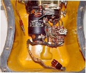
Detail view of interior with transmitter section (left) and aerial reel compartment (right). The latter bears much resemblance to that of the German NS2.
1000 Hz tone oscillator valve (type 12SC7). Click here for the circuit diagram. The aerial trimming capacitor rotated through 360 degrees, during half of which a switch closed, adding an extra capacitor. RF output was specified as 5 watts. The range of the SCR-578 was quoted as 200 miles to aircraft flying at 2000 ft.
Power was derived from a double-voltage hand generator, delivering 24 volts LT and 330 volts HT. The nominal turning speed, approximately 80 revolutions per minute, was much less than the German generator. In addition to radio transmission, the set could be used as a hand-powered signal light, automatically keyed or continuously, intended to be used for visual signalling by night if an aircraft was heard. The M-308 signal lamp was plugged into a socket provided and strapped on top of the head with the straps under the chin.
Superior
The mechanical construction of the US version known as BC-778, not much later affectionately called 'Gibson Girl', was superior to both German and British predecessors. It was manufactured in far greater numbers and remained in use and its later version AN/CRT-3 was kept in production long after World War 2.
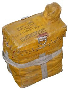
The SCR-578 consisted of a BC-778 transmitter unit and a number of accessories, (such as kite aerial, balloons with hydrogen generators) weighing 34 lb. Painted the usual bright yellow, it was completely packed in a single padded yellow canvas bag. The initial versions used two bags, the set proper and an accessories bag. When required for use, it was normally thrown from the ditched aircraft into the sea, along with the dinghy. It could also be dropped by a parachute, which was part of the set.
In the AUTO 1 position of the function switch the transmitter automatically alternated between SOS for 20 seconds and a continuous dash for 20 seconds. In the AUTO 2 position of the function switch the transmitter had the same function except that the code AA is transmitted in stead of SOS.
80 rpm
The transmitter of the BC-778 was not crystal controlled. It consisted of an ECO RF oscillator-RF output valve (type 12A6), operating on 500 kHz, grid modulated by a
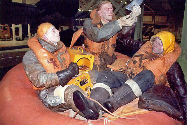
This cartoon, published in the SCR-578 handbook (above left) does not really reflex the hardship experienced by a ditched aircrew. This is rather realistically expressed in a diorama in the NZAF museum. ( Above right, click to enlarge)


British kite issued with T1333


A foldable box kite was part of the SCR-578


Complete SCR-578 packed in padded bag. The folded kite projects through the top cover.
 Top of page


Transmitter T-74/CRT-3 was part of the complete life raft set AN/CRT-3.
An operation instructions plate with Morse code was fitted to the top of the AN/CRT-3 (left). Internal view of the transmitter section (centre). The double voltage generator with gear and auto transmitter contacts (right).

German NS2 emergency transmitter
The Russian AVRA-45, (Cyrillic transcription ‘ABPA-45’) stands for ‘AVariyny Radioperedatchik’ (Emergency Transmitter), was produced from late 1945 onwards.
Photos, circuit diagram and further info courtesy RKK Radio Museum, Moscow.
Test test equipment for the AN/CRT-3.
Test Set TS-522/CRT-3 (right) was a performance test unit.
Antenna A-98 (Phantom) was an aerial dummy load for test purposes. (below)


Transmitter BC-778, part of SCR-578